Dover PSG BLACKMER MLN4B Скачать руководство пользователя страница 14

106-A00    Page 14/20 

MAINTENANCE: MLN4B, MRLN4B


PUMP ASSEMBLY 

Before reassembling the pump, inspect all component 
parts for wear or damage, and replace as required. 
Wash out the bearing/seal recess of the head and 
remove any burrs or nicks from the rotor and shaft.  
Remove any burrs from the liner (41). 

1. LINER 

– 

The liner has a close fit with the casing (12); 

take care to avoid finger injury during installation.


a.  Align and start the liner (41) and liner key (74) 

together into the pump casing. The word "INTAKE," 
which is cast into the liner, must be towards the 
intake side of the pump. NOTE: The intake port is 
marked with an inward facing arrow. 

b.  Lightly tap the outer edge of the liner with a plastic 

or lead hammer to fully insert it into the casing. 

2. DISC 


Before the disc is attached to the head, 

make sure both surfaces are clean and smooth.  

Gently file away any burrs or rough spots.


a.  Place a disc (71) on the head (20 or 20A) with the 

counter-bored screw holes facing up. 

b.  Position the disc so that 

when the head is 

mounted

 with the drain hole and V-notch down, 

the word "INTAKE" on the disc will be towards the 
intake side of the pump. The two disc holes must 
be in the 2 and 4 o'clock positions if the inlet is on 
the right (see Figure 10). 

c. 

Install the four lockwashers (71B), tangs outward, 
and machine screws (71 A) to attach the disc to the 
head. 


Figure 10 

3. 

HEAD ASSEMBLY


a.  To mount the head assembly (20) to the casing 

(12), first install the head O-ring (72) in the groove 
formed where the disc meets the head. 

b.  Grease the entire chamfer on the pump casing 

where the head O-ring will need to slide into 
position. 

c. 

Place the head assembly (20 or 20A) on the studs, 
with the V-notch and drain hole facing down 
(towards the bottom of the pump). 

d.  Check to make sure the word "INTAKE" on the disc 

is towards the intake side of the pump when the 
head is mounted. 

e.  Install and tighten the two nuts (21C) on the head 

studs. 

f. 

Install and tighten the head capscrews (21) uniformly, 
making sure the head O-ring (72) slides into place 
without damage. 

4. 

SLEEVE BEARINGS (Bushings) – 

If the sleeve bearing 

(24) has been removed from the hub (20C), a new bearing 
must be installed prior to attaching the hub assembly to 
the head. 

a.  To aid installation, heat the hub in an oven at 200°F 

(93°C) before installing the bearing. 

b.  Place the bearing (24) in the bearing bore on the 

inside face of the hub (20C) with the tapered end 
inward. 

c. 

Using an arbor press, press the bearing into the hub 
in one continuous motion, until it is flush with (or 
slightly below) the inside face of the hub. Starting and 
stopping the pressing motion may result in a cracked 
bearing. 

5. 

HUB ASSEMBLY


a.  Before attaching the hub assembly (20C) to the 

mounted head (20), grease the three head chamfers. 

b.  Install the hub O-rings (72A & 72B), and slide the hub 

(20C) onto the shaft with the V-notch of the hub 
towards the bottom of the pump. 

c. 

Install and tighten the two hub capscrews (21D) to pull 
the hub into place. BEGIN WORKING ON THE 
OPPOSITE SIDE OF THE PUMP. 

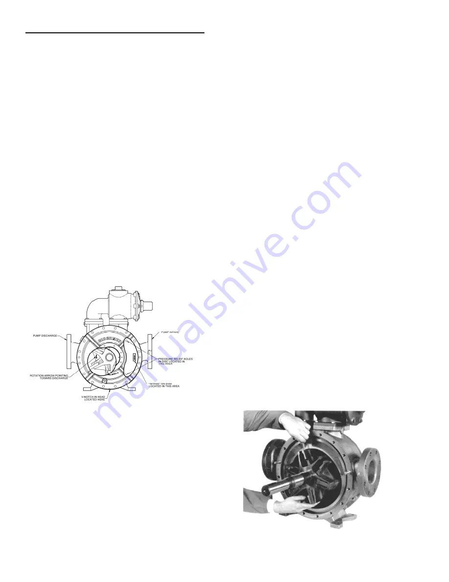
6.  ROTOR AND SHAFT – 

It is necessary to install the 

bottom vanes and the push rods in the rotor while inserting 
the rotor and shaft into the pump casing.


a.  Partially install the rotor and shaft (13) into the open 

side of the pump and through the bore of the installed 
head (20).  Be careful not to damage the disc face with 
the shaft end. 

NOTE: When installing the rotor and 

shaft, the rotation arrow on the rotor must point in 
the direction of pump rotation-towards the 
discharge side of the pump when the arrow is 
positioned directly below the shaft.  

See Figure 10. 

b.  Keep part of the rotor (13) outside the casing (12) such 

that the three bottom vanes  (14)(rounded edge 
outward) can be inserted into the rotor slots and held in 
place while all three push rods (77) are inserted.  See 
Figure 11.  

c.  The rotor and shaft (13), with the three bottom vanes 

(14) installed, can now be 

fully 

inserted into the casing 

(12). 

d.  Install the remaining vanes (14) in the top positions of 

the rotor. 


Figure 11 

Содержание PSG BLACKMER MLN4B

Страница 1: ...mer com or by contacting Blackmer Customer Service SAFETY DATA This is a SAFETY ALERT SYMBOL When you see this symbol on the product or in the manual look for one of the following signal words and be alert to the potential for personal injury death or major property damage Warns of hazards that WILL cause serious personal injury death or major property damage Warns of hazards that CAN cause seriou...

Страница 2: ...DENTIFICATION A pump identification tag containing the pump serial number I D number and model designation is attached to each pump Record and file the data from this tag for future reference If replacement parts are needed or if information pertaining to the pump is required this data must be furnished to a Blackmer representative MLX4B Full size liner External Ball Bearings MLXW4B MLX4B w Wear r...

Страница 3: ...ea of at least four times the area of the intake piping Strainers must be cleaned regularly to avoid pump starvation 4 The intake system must be free of air leaks 5 Expansion joints placed at least 36 0 9m from the pump will compensate for expansion and contraction of the pipes Contact the flexible connector hose manufacturer for required maintenance care and design assistance in their use 6 Insta...

Страница 4: ...ation and create undue stress on all attached components Never start a pump when it is rotating in the reverse rotation as the added starting torque can damage the pump and related equipment OPTIONAL JACKETED HEADS Hot oil or steam can be circulated through jacketed heads by connections at the NPT pipe plugs directly above and below the shaft for heating highly viscous liquids or to thaw out liqui...

Страница 5: ...ns provided These can be used to check actual suction and discharge conditions after pump start up 6 Check the wiring of the motor and briefly turn on the power to make sure that the pump rotates in the direction of the rotation arrow START UP PROCEDURES NOTICE Consult the General Pump Troubleshooting section of this manual if difficulties during start up are experienced 1 Start the motor Priming ...

Страница 6: ... the pump or pumping system from excessive pressure The valve is not meant to be used for prolonged recirculation When pumping highly volatile liquids under a high suction lift and cavitation or starving of the pump exists partial closing of the discharge valve will result in excessive noise in the relief valve Plumbing the relief valve so flow is directed back to the storage tank is recommended w...

Страница 7: ...ANCE STRAINERS Strainers must be cleaned regularly to avoid pump starvation Schedule will depend upon the application and conditions LUBRICATION NOTICE To avoid possible entanglement in moving parts do not lubricate pump bearings gear reducer or any other parts while the pump is running NOTICE If pumps are repainted in the field ensure that the grease relief fittings 76A are functioning properly a...

Страница 8: ...use of wire hooks carefully pull the rotating seal assembly jacket seal face O ring 153B 153E out of the head and off the shaft Holes in the seal jacket will facilitate the removal 7 Remove the head capscrews 21 and head stud nuts 21C Two jackscrew holes are provided in the rim of the head to facilitate removal 8 Remove the head 20 or 20A from the casing 12 being careful not to nick or scrape the ...

Страница 9: ...ten the head capscrews 21 uniformly making sure the head O ring 72 slides into place without damage 4 Attach one hub 20C and bearing 24 to the mounted head without O rings or mechanical seal components Install and snug up the hub capscrews 21D NOTE This step is intended as an assembly aid and is essential to help guide the rotor and shaft into place without damaging the mechanical seal The remaini...

Страница 10: ...this time including the mechanical seal and O rings see Step 8 for mechanical seal instructions Lightly grease the shaft and the head chamfers before installing the assembly to enable the O rings to slide into place without damage Reinstall the bearing spacer 24D 12 LOCKNUT INSTALLATION The bearing locknuts 24A and lockwashers 24B MUST be installed and adjusted properly Overtightening locknuts can...

Страница 11: ...t protector 185 into the bearing cover 27 on the non driven end of the pump 16 RELIEF VALVE ASSEMBLY if equipped a Insert the valve 9 into the relief valve body 6 with the fluted end inward b Install the relief valve spring 8 spring guide 7 and guide rod 45 against the valve c Attach a new relief valve gasket 10 and the valve cover 4 on the cylinder d Screw the relief valve adjusting screw 2 into ...

Страница 12: ... the appropriate procedures and warnings as presented in this manual SCHEDULED MAINTENANCE STRAINERS Strainers must be cleaned regularly to avoid pump starvation Schedule will depend upon the application and conditions LUBRICATION NOTICE To avoid possible entanglement in moving parts do not lubricate gear reducer or any other parts while the pump is running Sleeve bearings bushings are lubricated ...

Страница 13: ...e the head 20 or 20A from the casing 12 being careful not to nick or scrape the shaft 7 The disc 71 will come off with the head assembly and is attached with four countersunk allen head machine screws 71A and lockwashers 71B 8 From the open side of the pump grasp the rotor in the 3 and 9 o clock positions and gently pull the rotor and shaft 13 out of the head assembly remaining on the casing CAUTI...

Страница 14: ...o nuts 21C on the head studs f Install and tighten the head capscrews 21 uniformly making sure the head O ring 72 slides into place without damage 4 SLEEVE BEARINGS Bushings If the sleeve bearing 24 has been removed from the hub 20C a new bearing must be installed prior to attaching the hub assembly to the head a To aid installation heat the hub in an oven at 200 F 93 C before installing the beari...

Страница 15: ...n after 20 30 minutes of running the pump and readjust if necessary NOTE Some leakage is desirable to lubricate the packing but in some cases is unacceptable depending on the application 10 BLACKMER TRIPLE LIP SEAL if equipped On pumps equipped with a Blackmer triple lip seal refer to the separate literature accompanying the triple lip seal for installation instructions 11 COMMERCIAL MECHANICAL SE...

Страница 16: ...he discs with a clean cloth and alcohol to remove any dirt or foreign particles MLX Models Improper locknut adjustment Locknuts must be adjusted properly to center the rotor and shaft between the heads Refer to Locknut Installation on Page 10 MLN Models Excessively tight packing Refer to Packing Adjustment on Page 15 MLX MLN Models Contaminated mechanical seal faces Any trace of grease or dirt on ...

Страница 17: ...r specific application Continual or long term bypassing of liquid through relief valve Check for restriction in the discharge line or an improper relief valve adjustment See Relief Valve on Page 6 OTHER POSSIBLE CAUSES OF NOISE AND VIBRATION Excessively worn vanes liner or discs Bearing Worn or Damaged Loose or improperly installed piping Misalignment of pump and driver Pump base not properly moun...

Страница 18: ...r pressure spikes Pump driver driveline drive shaft misalignment Excessively worn vanes or vane slots Settled or solidified material in the pump at start up Overtightened V belts if used SEAL LEAKAGE Probable Cause O rings not compatible with the liquids pumped O rings nicked cut or twisted Shaft at seal area damaged worn or dirty Ball bearings overgreased Pump sleeve bearings worn excessively Exc...

Страница 19: ...106 A00 Page 19 20 NOTES ...

Страница 20: ... 215 GPM HXL 6 8 10 Sliding Vane Pumps 130 to 2 220 GPM Refineries Terminals Barges Ships Reciprocating Gas Compressors Liquefied Gas Transfer Boosting Vapor Recovery Hand Operated Pumps Dispensing Transfer In line Accessories Gear Reducers Bypass Valves Strainers Visit www blackmer com for complete information on all Blackmer products 1809 Century Avenue Grand Rapids Michigan 49503 1530 U S A Tel...

Отзывы: