background image

Lit. No. B64093, Rev. 09 

30 

April 15, 2011

POWER HITCH™ SYSTEM INSTRUCTIONS

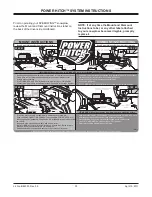
Prior to operating your SPEEDWING™ snowplow, 
review the Mount and Dismount Instructions label on 
the back of the driver-side moldboard.

NOTE: If at any time the Mount and Dismount 
Instructions label, or any other label attached 
to your snowplow, becomes illegible, promptly 
replace it.

•  Kickstand must be lowered, with kickstand pin seated in lower hole on pivot beam.
•  Slowly drive vehicle forward until pushbeam receiver mount points contact 

A-frame mount bushings.

•  Turn POWER HITCH OPERATION switch (on plow control) to "ON" position.
•  Connect plow and vehicle electrical harnesses. Connect weather caps together.

•  Raise plow. Lower kickstand until kickstand pin is seated in lower hole on pivot beam.
•  Lower plow on flat, level surface. Turn vehicle ignition off.
•  Remove hitch pins from A-frame and undercarriage.
•  Turn vehicle ignition on.
•  Turn POWER HITCH OPERATION switch (on plow control) to "ON" position.

•  Pull A-frame latch lock pin out and lower A-frame latch over draw pin.
•  Push and hold CONNECT/DISCONNECT switch upward. POWER HITCH arm 

will engage back of pushbeam and pull plow into pushbeam receiver mount points 
on vehicle.

•  Insert both hitch pins and secure each with hair pin cotter.
•  Lower POWER HITCH arm to relieve tension on A-frame latch. Raise A-frame 

latch and lock into position with lock pin. Raise plow.

•  Raise kickstand until kickstand pin seats into upper hole on pivot beam.

•  Push and hold CONNECT/DISCONNECT switch downward. POWER HITCH arm 

will disengage from behind undercarriage pushbeam and lower.

•  Disconnect plow and vehicle electrical harnesses. Install weather caps.
•  Turn SYSTEM POWER (on plow control) to "OFF" position.
•  Slowly move vehicle backward away from plow.

MOUNT INSTRUCTIONS

DISMOUNT INSTRUCTIONS

Read Owner's Manual for Complete Instructions.

Read Owner's Manual for Complete Instructions.

WARNING: Keep fingers away from plow and truck mounting points.

WARNING: Keep fingers away. POWER HITCH arm raises behind undercarriage pushbeam.

A-Frame
Latch

Hitch
Pin

A-Frame
Latch
Lock Pin

Draw
Pin

A-Frame Latch

rotates clockwise

and hooks onto

Draw Pin

CONNECT/DISCONNECT
POWER HITCH Switch

Adjustable
Kickstand

Adjustable
Kickstand

A-Frame
Mount Bushing

Pushbeam
Receiver 
Mount Points

POWER
HITCH Arm

Slowly Move
Vehicle Forward

Slowly

Move Vehicle

Backward

Undercarriage
Pushbeam

CONNECT/DISCONNECT
POWER HITCH Switch

CONNECT/DISCONNECT
POWER HITCH Switch

POWER
HITCH Arm

POWER HITCH Arm

Hitch

Pin

Kickstand Pin

Kickstand Pin

Adjustable
Kickstand

Kickstand Pin

STEP #1

STEP #1

STEP #2

STEP #2

44812

U.S. Patents 5,638,618; 5,899,007; 6,178,669; 6,276,076; 6,393,737; 6,408,549; 6,412,199; 6,442,877; 6,615,513; Canadian and other patents pending.

Содержание BLIZZARD SPEEDWING 760SW

Страница 1: ...date CAUTION Read this document before operating or servicing snowplow CAUTION See your BLIZZARD sales outlet Web site for specific vehicle application recommendations before installation The Underca...

Страница 2: ...operation and maintenance information for your new BLIZZARD snowplow To keep your snowplow in good condition read and understand this manual and follow its recommendations Failure to do so may affect...

Страница 3: ...owplow Side 19 Electrical Schematics Snowplow Side 20 Electrical Installation Vehicle Side 23 Electrical Schematics Vehicle Side 26 TABLE OF CONTENTS POWER HITCH SYSTEM INSTRUCTIONS 30 TESTING YOUR SN...

Страница 4: ...A frame latch and lock into position with lock pin Raise plow Raise kickstand until kickstand pin seats into upper hole on pivot beam Push and hold CONNECT DISCONNECT switch downward POWER HITCH arm...

Страница 5: ...uld result in serious personal injury CAUTION See your BLIZZARD outlet for application recommendations CAUTION Plowing speed should not exceed 10 mph CAUTION Transport speed should not exceed 45 mph F...

Страница 6: ...ractions and pay attention to the road Wait until it is safe to operate Mobile Communication equipment such as cell phones or two way radios VENTILATION BATTERY SAFETY NOISE Airborne noise emission du...

Страница 7: ...es as the vehicle is loaded with cargo or other truck equipment or snowplow accessories are installed If there is uncertainty as to whether available capacity exists the actual vehicle as configured m...

Страница 8: ...transporting large volumes of snow final clean up Ideal application residential driveways small roads roadway intersections D Angled Width with Trailing Wing 6 7 or 7 10 Blade Width To angle your bla...

Страница 9: ...ylene material should be removed from the pallet for easy access to the snowplow 3 Due to the odd shaped components and size of several assembly parts various cable ties and corrugated material are us...

Страница 10: ...09 ft lb 9 16 12 16 400 115 ft lb 154 ft lb 5 8 11 14 500 113 ft lb 151 ft lb 5 8 11 20 300 159 ft lb 211 ft lb 3 4 10 21 300 200 ft lb 266 ft lb 3 4 10 30 100 282 ft lb 376 ft lb 7 8 9 29 435 321 ft...

Страница 11: ...f seal and reduction of flow N A 03 8 9 2 04 11 12 2 05 14 15 1 1 2 06 18 20 1 1 2 08 36 39 1 1 2 10 57 63 1 1 4 12 79 88 1 14 94 103 1 16 108 113 1 20 127 133 1 24 158 167 1 32 245 258 O Ring Boss To...

Страница 12: ...one bushing through each mounting hole and secure with retaining rings 3 Mount the kickstand to the end of the pivot beam driver s side using the 1 2 x 4 1 2 cap screw provided The spring bushing and...

Страница 13: ...45 end of the hose to the hydraulic adapter on the cylinder Both hoses should be routed through the triangular openings in the A frame Tighten fittings and hoses per torque chart 4 Position each angl...

Страница 14: ...lates and the A frame NOTE The A frame latch located at the rear center of the A frame should be raised up to insert the draw latch mount pin Pull the A frame latch pull pin out and rotate the latch c...

Страница 15: ...ave this hardware to be reused later Align the mount holes in the pump with the holes in the bracket located on the A frame Insert 3 8 x 1 3 4 threaded stud with a 3 8 locknut through the bottom mount...

Страница 16: ...D A FRAME ASSEMBLY 11 Secure the manifold to the A frame Align the mount holes with the A frame brackets Properly replace and tighten all hardware NOTE A medium strength threadlocking compound should...

Страница 17: ...ENERAL SYSTEM SCHEMATICS HYDRAULIC SCHEMATIC RAISE S6 TGP PGP S3 T1 P1 S4 CB2 CB1 3000 PSI 1200 PSI 1200 PSI RIGHT ANGLE LEFT ANGLE 1 S5 2 3 S8 LOWER FC LIFT CYL 4 RV1 ELECTRICAL SCHEMATIC A D B C H F...

Страница 18: ...ment NOTE Energize the following solenoids for the functions S3 Angle Left Passenger Side Cylinder S4 Angle Right Driver Side Cylinder S5 Float S6 Raise Lift Cylinder Base S5 S8 Lower Lift Cylinder Ro...

Страница 19: ...Attach the connector on the snowplow harness to the switch NOTE Use caution when connecting Switches can break if this is done forcefully The pump cover installs over the top of the draw latch switch...

Страница 20: ...4 STRIPE COLOR BLACK WIRE COLOR BLUE PIN NUMBER STRIPE COLOR WHITE WIRE COLOR RED PIN NUMBER EXAMPLE 7 6 15 STRIPE COLOR BLACK WIRE COLOR PINK PIN NUMBER STRIPE COLOR WHITE WIRE COLOR BLUE PIN NUMBER...

Страница 21: ...ORG ORG BLK ORG RED ORG WHT WHT ORG TOP 3 7 1 4 5 8 2 6 1 BRN 2 BRN 3 ORG RED 4 WHITE 5 PNK BLK 6 PNK BLK D C B A E C WHT A ORG BLK B ORG WHT D ORG RED E LT GRN G F H J K F BLU WHT ORG RED ORG WHT ORG...

Страница 22: ...G ORG WHT WHT WHT WHT ORG RED ORG RED BLK RED WHT BLU WHT BLU BLU BLK WHT C RED BLK RED WHT K J BLU WHT ORG RED BLU BLU BLK G H F LT GRN D E ORG WHT ORG BLK B A PINK BLK ORG RED ORG RED PINK BLK 6 LT...

Страница 23: ...o areas that come in contact with moving engine parts or become extremely hot The harness could become tangled and or melt causing electrical failure and vehicle damage 3 Connect the vehicle harness g...

Страница 24: ...ear the bumper Cable tie the plug to the vehicle bumper or tow hook to keep the harness from hanging too low 11 Install the remainder of the vehicle wire harness to the interior of the cab Find an acc...

Страница 25: ...wo caps that install on the ends of the light tower After adding a liberal amount of dielectric grease connect the terminals from the snowplow headlamps to the terminals on the main lighting harness 1...

Страница 26: ...8 4 3 WHT LIFT BLU WHT LEFT SLIDE BOX EXTEND BLK GROUND BLU BLK LEFT SLIDE BOX RETRACT ORG FLOAT RED SWITCHED 12 VOLT DC RED 1 RED WHT RIGHT SLIDE BOX EXTEND B A BLK 10 6 7 8 11 15 16 2 3 4 5 13 14 1...

Страница 27: ...RED BLK 1 2 BRN RED WHT RED BLK BLU WHT 4 5 BLK 11 ORG BLU BLK BLU LT GRN WHT 9 7 8 10 PNK BLK 15 LT GRN BLU WHT RED WHT RED BLK BLU BLU BLK ORG WHT PNK BLK BLK GRN YEL RELAY LIGHTING HARNESS B A BLK...

Страница 28: ...LOCK CONNECTOR USED IN INSTALLATION OTHER WIRE GRAY WIRE 87 87a 87a 30 87 85 301 87a1 B1 301 861 30 85 861 871 871 87a1 851 86 86 87 YEL BLK 86 BLK WHT 30 YEL 85 GRN YEL 87a1 YEL RED 871 LT GRN BLK 86...

Страница 29: ...GRY F HIGH BEAM YEL BLK A COMMON WHT E LOW BEAM LT GRN BLK PNK LT GRN RED GRN YEL BLK WHT YEL RED YEL YEL BLK LT GRN LT GRN BLK A LT GRN RED LOW BEAM GRY B GROUND BLK C RIGHT TURN PNK D PARK RUN GRY...

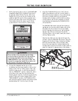
Страница 30: ...HITCH arm to relieve tension on A frame latch Raise A frame latch and lock into position with lock pin Raise plow Raise kickstand until kickstand pin seats into upper hole on pivot beam Push and hold...

Страница 31: ...m The action of the arm moves the snowplow toward the vehicle and into position for proper attachment 3 Align the POWER HITCH arm on the A frame below the pushbeam with the receiver plates in line wit...

Страница 32: ...e blade contacts the ground The LED FLOAT light touchpad only will come ON when the snowplow is in FLOAT mode Angle the snowplow to the right by moving the joystick toward the R right angle on the lab...

Страница 33: ...ast as specified in the Undercarriage Selection Guide e Check functioning of any automatic vehicle leveling systems and specific manufacturer s instructions pertaining to vehicle preparation for headl...

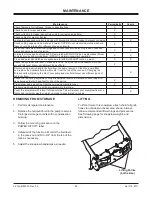
Страница 34: ...should be retained for different shoe adjustments X Clean and lubricate all electrical plugs and connections with dielectric grease Clean and install all dust caps prior to storing X X Lubricate all...

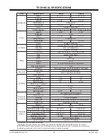
Страница 35: ...Aluminum Valves Electro Hydraulic Cartridge Cylinders Angle Cylinders 2 Stroke 10 12 Ram Diameter 1 3 4 2 Bore Diameter 2 2 1 4 Raise Lower Cylinders 1 Stroke 4 5 8 Ram Diameter 1 1 4 Bore Diameter 2...

Страница 36: ...evel in the pump reservoir is low Fluid is leaking Add fluid to within 3 4 from the top of the tank Check for leaks around the pump manifold and cylinders System pressure may be set too low Increasing...

Страница 37: ...ly You can die or be seriously injured Drop snowplow to ground before adjusting flow control Turn flow control valve counterclockwise in small increments and test Review all probable causes for Snowpl...

Страница 38: ...Lit No B64093 Rev 09 38 April 15 2011 MOLDBOARD WING PARTS ALL MODELS 25 1 2 3 19 18 17 20 8 9 10 11 13 14 15 16 12 5 6 7 21 4 22 23 24 Pin must be installed and or replaced from the bottom 5A 8A...

Страница 39: ...8 x 1 Hex Cap Screw G5 9 91332 4 4 5 16 18 Hex Locknut Topring GB 10 96323 1 Label Wing DS 96327 1 Label Wing DS 11 B53021 1 Wing DS B53062 1 1 Wing DS 12 B61608 1 Wing Cutting Edge T1 DS B61610 1 Win...

Страница 40: ...0 41 39 5 6 1 34 35 27 25 33 31 32 30 34A Qty Item Part 760SW 860SW Description 1 B41056 1 Pivot Beam B41066 1 Pivot Beam 2 B40124 4 3 4 x 6 Clevis Pin 95739 4 3 4 x 5 Clevis Pin 3 90601 7 7 1 4 x 1 1...

Страница 41: ...Topring 24 B61629 1 1 3 8 16 x 2 1 8 Stud 25 B62038 1 1 Toggle Switch DPDT ON OFF ON 16A 115V AC 26 B82061 1 Clevis Pin B40124 1 Clevis Pin 27 B61295 1 1 Label POWER HITCH Connect Disconnect Switch B...

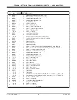
Страница 42: ...093 Rev 09 42 April 15 2011 DRAW LATCH FINAL ASSEMBLY PARTS ALL MODELS 15 16 13 14 9 5 4 20 17 23 29 25 24 27 26 18 19 21 22 2 3 8 7 10 11 1A 12 1 6 28 Used to lock wings in straight position Includes...

Страница 43: ...aw Pin Latch Plate Hydraulic Cylinder Rod End B40042 2 3 4 x 2 1 2 Draw Pin Latch Arm Pivot Pin Hydraulic Cylinder Rod End 11 B82024 1 3 4 x 2 3 8 Draw Pin Latch Arm Pivot 12 B40093 1 1 1 1 4 OD x 1 1...

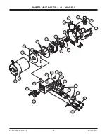
Страница 44: ...Lit No B64093 Rev 09 44 April 15 2011 POWER UNIT PARTS ALL MODELS 1A 3 4 26 5 6 15 16 17 18 20 21 22 19 14 28 14A 8 9 1 10 25 11 12 13 2 27 24 23 7...

Страница 45: ...050 1 Plug Hollow Hex Male ORB 16 B60173 1 Coupling Test Port Nipple 17 B60461 2 Cartridge Valve 3 Way 2 Position 18 B62237 2 Coil 10V DC 10 Size 19 B62246 1 Coil Harness Assembly incl items 18 21 B62...

Страница 46: ...Rubber Snowplow Side ns B62046 1 1 Electric Connector Female Plastic ns B62093 10 10 Terminal Female 18 16 ga ns B61439 2 2 Cable Tie 15 Black ns B62167 1 1 Harness Diode Loop 3 B62150 1 1 Harness Veh...

Страница 47: ...1 1 Control Station Joystick 15 B63106 1 1 Label Snowplow Power Switch ON OFF BLZ 1061 16 B61185 1 1 Base Plate Joystick Control Station 1 8 ABS Plastic 17 B61127 1 1 61 Hook and Loop Fastener Strap...

Страница 48: ...i max from the vehicle pump and 2 3 gpm output 2500 psi max to the existing hydraulic manifold Hydraulic hoses fittings and pump not included 1 The snowplow airfoil helps channel air flow to your truc...

Страница 49: ...requirement Sand bags are recommended for use as ballast NOTE Ballast recommended and its weight calculations assume the entire width of the bed is filled as close to tailgate as possible 5 This adjus...

Страница 50: ...B61630 1 Hardware Kit Snowplow Assembly Parts ns B61651 1 Snowplow Airfoil ns B60448 1 1 Hydraulic Adapter Kit incl items 56590 3 B60007 B60272 4 ns B60449 1 1 Hydraulic Hose Kit incl items B60273 B6...

Страница 51: ...Lit No B64093 Rev 09 51 April 15 2011 NOTES...

Страница 52: ...the vehicle manufacturer may require or recommend optional equipment for snow removal Do not exceed vehicle ratings with a snowplow This product is manufactured under the following U S patents 5 420...

Отзывы: