2
3
/
8
"
60 mm
a
b
c
d
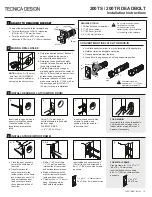
200TS / 200TR DEADBOLT
Installation Instructions
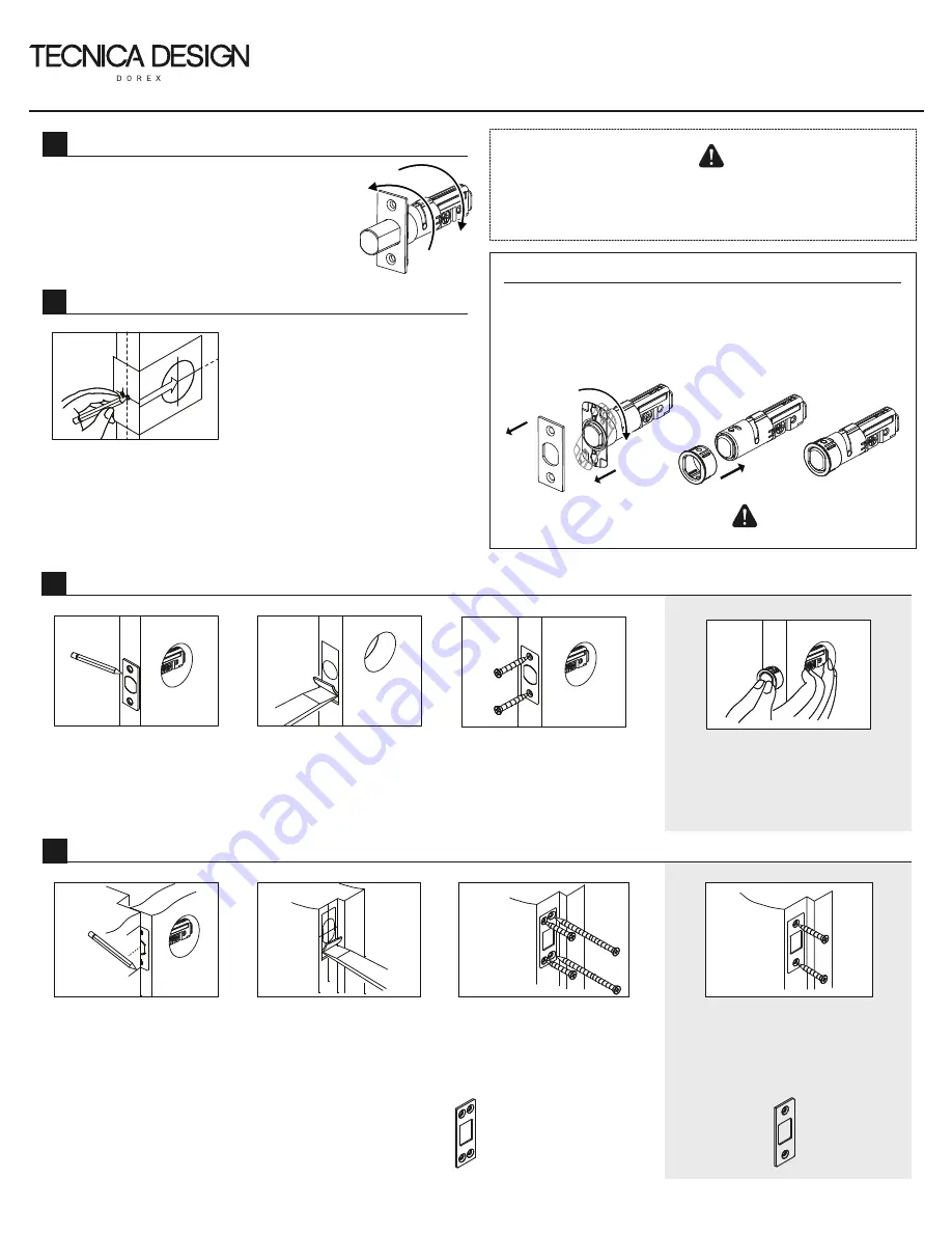
MARK & DRILL HOLES
2
To adjust the backset hold the faceplate and :
a. Turn the latch to the RIGHT or clockwise
(CW) for a 2
3
/
4
" (70 mm) backset .
b. Turn the latch to the LEFT or counter-
clockwise (CCW) for a 2
3
/
8
" (60 mm) backset.
CONVERT MORTISE LATCH TO DRIVE-IN
a. Use flat-head screw driver to pry the faceplate off the backplate
b. Rotate or twist the backplate clockwise.
c. Remove backplate from the latch.
d. Insert drive-in ring as shown until ring snaps into position.
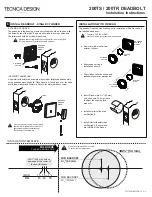
INSTALL DEADBOLT LATCH (WOOD DOOR)
3
Insert latch in edge hole and
orient it vertically as shown.
Trace the outline of the
faceplate and remove the
latch.
Chisel
5
/
32
" (4 mm) deep or
until the faceplate is flush with
the door edge.
FACEPLATE SIZE:
1 x 2
1
/
4
" (25.4 x 57 mm)
Insert latch and secure with
screws. To avoid wood
splitting, drill pilot holes for
the screws first.
a. Close the door as shown
to mark the centerline of
the strike.
b. Transfer horizontal
centerline mark to the
inside surface of the frame
and measure one half (½)
the door thickness from
the door stop to locate
the vertical centerline of
the strike.
c. Drill a 1" (25.4 mm) hole
1
1
/
4
" (32 mm) deep at the
intersection of the vertical
and horizontal centerlines.
d. Match strike screw holes
with vertical centerlines on
jamb and trace outline.
e. Chisel outline
1
/
16
" (1.5 mm)
deep. Strike should be
flush with jamb surface.
FOR DRIVE-IN
Insert latch in to the hole as shown
until flush with door edge. Use a
rubber mallet or wood block and
hammer if necessary.
INSTALL STRIKE (WOOD FRAME)
4
a, b
c, d, e
g
200TS-TR-INST 2018-03 1/2
REQUIRED TOOLS:
1. Phillips flat-head screwdriver
2. 1" (25.4 mm) chisel
3. 1" (25.4 mm) drill bit
4. 2
1
/
8
" (54 mm) hole saw
Do not use power tools when
installing door harware,
excessive screw or bolt
tightening may affect installation
or functioning of the hardware.
ADJUST TO REQUIRED BACKSET
ADJUST TO REQUIRED BACKSET
1
b
a
FACEPLATE
c
BACKPLATE
LATCH
DRIVE-IN
RING
d
a. Determine desired backset. Backset
on door should be the same as
backset of the deadbolt latch.
b. Determine the desired lock height
from the finished floor and mark the
lock's height centerline.
c. Fold template over door edge at
marked height and mark the center of
the 2
1
/
8
" (54 mm) hole on door surface
at required backset and drill.
d. Determine thickness of the door and
make center mark for 1" (25.4 mm) on
the door edge and drill. Drill
31
/
32
"
(25 mm) for drive-in installations.
NOTE:
Drill the 2
1
/
8
" (54 mm)
hole from BOTH SIDES of
the door to avoid splitting or
damaging the door surface.
f
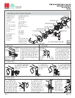
FOR METAL FRAME
Prepare frame for 1
1
/
8
x 2
3
/
4
x
1
/
16
"
(29 x 70 x 1.6 mm) strike.
Insert strike and secure using
#8 x 1
1
/
8
" (32 mm) combo screws
as shown.
Insert strike and secure using 3"
(76 mm) long wood screws and
#8 x 1
1
/
8
" (32 mm) combo screws
as shown.
1
1
/
8
x 2
3
/
4
",
1
/
4
"
radius corners
29 x 70
mm
, 6
mm radius corners
1
1
/
8
x 2
3
/
4
"
29 x 70
mm
LATCH
FACEPLATE
2
3
/
4
"
70 mm
We recommend an
edge-bore of
31
/
32
" (25 mm)
diameter for a tighter fit.


