37
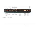
Up to 5 cables will come from the roof of the vehicle into the vehicle where the Core Module
will be installed; the df antenna coaxial cable, the df antenna control cable, the GPS receiver
cable, the radio modem coaxial cable, and the compass cable. Connect these cables to the
proper connectors on the core module.
You cannot use the compass and yaw rate sensor at the same time. If using the yaw rate
sensor mount it securely in the vehicle parallel to the floor of the vehicle and connect to the
compass input. It is also necessary to use the MPT User Interface software to set the compass
port (port 2) data rate to 38.4 kBaud.
If you are using an external scan receiver connect the external speaker output of the receiver
to the AUX IN connector and connect the audio output connector to the line input of the
computer using the 1/8 inch stereo cable supplied with the unit. If you purchased a
computer with the DDF7011, it will come furnished with a iMic (USB-to-Audio) converter that
has a line input. If your computer does not have a line input and you are going to use an
external scan receiver then you will need to purchase an audio interface.
The radio modem is used to communicate with other Doppler radio direction finders in the
event that the other direction finders cannot be networked on an Ethernet (IP) network. Each
radio modem has four preprogrammed channels. Set all the direction finders on the radio
modem network to the same channel.
The Ethernet connection is connected directly to the computer using a crossover cable
(orange cable).
The unit is powered using 12 volts. The DDF7011 without a laptop draws requires 13 watts. If
a laptop is connected to the laptop power supply the unit can draw up to 100 watts
depending on the battery's level of charge, so it is recommended that two cigar lighter plugs
and two power cables be used. Failure to use 2 cables may result in an under voltage
(particularly when starting the vehicle) causing the direction finder to reset.
Содержание DDF7011
Страница 1: ...USER S GUIDE DDF7011 AND DDF7012 USERS MANUAL ...
Страница 2: ......
Страница 6: ......
Страница 17: ...11 DDF7011 Installation and Setup Figure 8 Arrangement of the antenna element mounting hardware ...
Страница 24: ...18 DDF7011 and DDF7012 Users Manual User s Guide Figure 15 TU Antenna Mast Installed ...
Страница 25: ...19 DDF7011 Installation and Setup Figure 16 THF Antenna Frame Installed on Mast ...
Страница 28: ......
Страница 29: ...23 23 CORE MODULE CONNECTIONS Figure 17 below shows the front panel of the Core Module ...
Страница 30: ......
Страница 31: ...25 25 Figure 19 Fixed Site Core front panel connections ...
Страница 32: ......
Страница 34: ......
Страница 38: ...32 DDF7011 and DDF7012 Users Manual User s Guide Figure 20 VHF and UHF antenna arrangement ...
Страница 40: ......
Страница 41: ...35 Figure 22 Mobile core module connections ...
Страница 42: ......
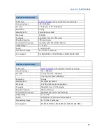
Страница 44: ...38 DDF7011 and DDF7012 Users Manual User s Guide Appendix SPECIFICATIONS ...
Страница 46: ......


