


81
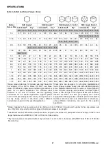
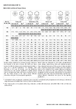
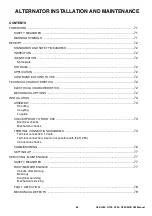
G60, G80, G100, G150, G200-SIIIA OM Manual
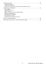
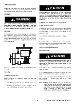
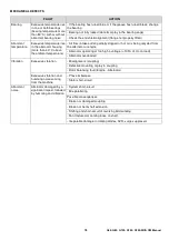
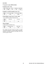
Checking the diode bridge
A diode in good working order should allow the current to
flow only in the anode-to cathode direction.
Checking the windings and rotating diodes using
separate excitation
During this procedure, make sure that the alternator
is disconnected from any external load and inspect
the terminal box to check that the connections are
fully tightened.
1.
Stop the unit, disconnect and isolate the AVR wires.
2.
There are two ways of creating an assembly with
separate excitation.
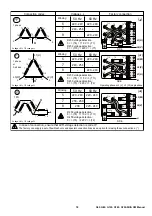
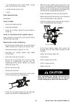
Assembly A:
Connect a 12 V battery in series with a
rheostat of approximately 50 ohms - 300 W and a diode
on both exciter field wires (5+) and (6-).
Assembly A
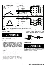
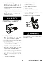
Assembly B:
Connect a “Variac” variable power supply
and a diode bridge on both exciter field wires (5+) and
(6-).
Both these systems should have characteristics which
are compatible with the field excitation power of the
machine (see the nameplate).
3.
Run the unit at its rated speed.
4.
Gradually increase the exciter field current by
adjusting the rheostat or the variac and measure the
output voltages on L1 - L2 - L3, checking the
excitation voltage and current at no load (see the
machine nameplate or ask for the factory test report).
When the output voltage is at its rated value and
balanced within 1% for the rated excitation level, the
machine is in good working order. The fault therefore
comes from the AVR or its associated wiring (i.e.
sensing, auxiliary windings).
Assembly B
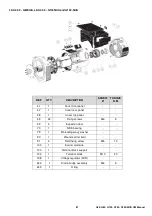
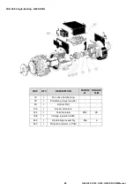
DISMANTLING, REASSEMBLY (SEE PAGE 86).
CAUTION
During the warranty period, this operation should
only be carried out in an LEROY-SOMER approved
workshop or in our factory, otherwise the warranty
may be invalidated. Whilst being handled, the
machine should remain horizontal (rotor not locked
in position). Check how much the machine weighs
before choosing the lifting method.
Tools required
To fully dismantle the machine, we recommend using the
tools listed below:
•
1 ratchet s extension
•
1 torque wrench
C
A
A n o d e
C a t h o d e
-
-
+
+
~
~
~
C C C
A A A
C C C
A A A
~
~
~
-
C
A
+
-
C
A
+
6 -
5 +
Diode 1A
12V battery
Rh. 50
Ω
- 300W
-
+
ASSEMBLY A
Exciter field
Diode 1A
-
+
6 -
5 +
Variac
AC
220V
DC
12V
50
60
70
08
90
100
40
30
02
10
0
ASSEMBLY B
Exciter field
Содержание G06030001
Страница 2: ......
Страница 4: ...4 G60 G80 G100 G150 G200 SIIIA OM Manual ...
Страница 5: ...5 G60 G80 G100 G150 G200 SIIIA OM Manual FOREWORD CONTENTS FOREWORD 6 DECLARATION OF CONFORMITY 7 ...
Страница 8: ...8 G60 G80 G100 G150 G200 SIIIA OM Manual ...
Страница 9: ...9 G60 G80 G100 G150 G200 SIIIA OM Manual ...
Страница 10: ...10 G60 G80 G100 G150 G200 SIIIA OM Manual ...
Страница 14: ...14 G60 G80 G100 G150 G200 SIIIA OM Manual ...
Страница 89: ......
Страница 90: ......


