


52
G60, G80, G100, G150, G200-SIIIA OM Manual
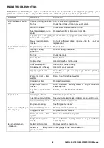
MAINTENANCE / 500 HOURS (CONT’D)
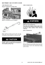
3.
Using the gauge (A) on the alternator bracket, stretch
belt by prying outward on alternator front frame.
Stretch the belt 1 gauge unit for a used belt and 1.5
gauge units for a new belt.
4.
Tighten cap screws (B) and (C).
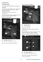
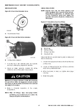
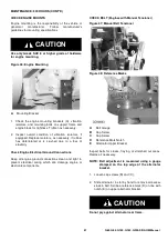
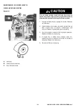
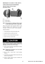
CHECK BELT (Engines with Automatic Tensioner)
Figure 49: Automatic Belt Tensioner
NOTE: With the belt loosened, inspect pulleys and
bearings. Rotate and feel for hard turning or
any unusual sounds. If pulleys or bearings
need replacement, see your John Deere
dealer.
Belt drive systems equipped with automatic (spring) belt
tensioners cannot be adjusted or repaired. The automatic
belt tensioner is designed to maintain proper belt tension
over the life of the belt. If tensioner spring tension is not
within specification replace tensioner assembly.
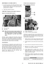
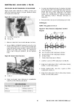
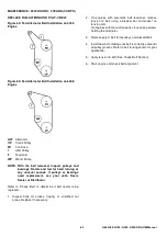
Check belt wear
The belt tensioner is designed to operate within the limit
of arm movement provided by the cast stops (A and B)
when correct belt length and geometry is used. If the
tensioner stop on swing arm (A) is hitting the fixed stop
(B), check mounting brackets (alternator, belt tensioner,
idler pulley, etc.) and the belt length. Replace belt as
needed (see Replace Fan and Alternator Belt,
Maintenance/As Required Section).
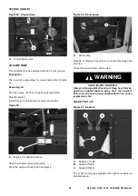
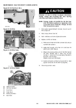
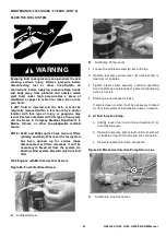
Check tensioner spring tension
Figure 50: Marks on Tensioner
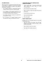
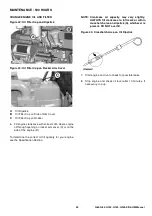
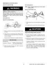
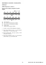
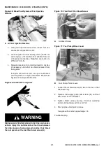
Figure 51: Align Marks
A belt tension gauge will not give an accurate measure of
the belt tension when automatic spring tensioner is used.
Measure tensioner spring tension using a torque wrench
and procedure outlined below:
1.
Release tension on belt using a long-handled 1/2 inch
drive tool in tensioner arm. Remove belt from pulleys.
2.
Release tension on tensioner arm and remove drive
tool.
3.
Put a mark (A) on swing arm of tensioner as shown.
4.
Measure 21 mm (0.83 in.) from mark (A) and put a
mark (B) on tensioner mounting base.
5.
Install torque wrench in square hole so that it is
aligned with center of roller and tensioner as shown.
Rotate the swing arm using a torque wrench until
marks (A and B) are aligned.
6.
Record torque wrench measurement and compare
with specification below. Replace tensioner assembly
as required.
A
Tensioner Stop
B
Fixed Stop
A
Mark on Swing Arm
B
Mark on Tensioner Mounting Base
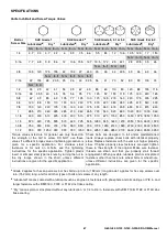
SPECIFICATIONS
Spring—Force
18—22 N·m (13—16 lb.-ft.)
Содержание G06030001
Страница 2: ......
Страница 4: ...4 G60 G80 G100 G150 G200 SIIIA OM Manual ...
Страница 5: ...5 G60 G80 G100 G150 G200 SIIIA OM Manual FOREWORD CONTENTS FOREWORD 6 DECLARATION OF CONFORMITY 7 ...
Страница 8: ...8 G60 G80 G100 G150 G200 SIIIA OM Manual ...
Страница 9: ...9 G60 G80 G100 G150 G200 SIIIA OM Manual ...
Страница 10: ...10 G60 G80 G100 G150 G200 SIIIA OM Manual ...
Страница 14: ...14 G60 G80 G100 G150 G200 SIIIA OM Manual ...
Страница 89: ......
Страница 90: ......