INSTALLATION MANUAL
EN
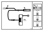
made. When this has been done, reconnect the distributor (6) to the
connector (8) marked “OUT” positioned on the shorter wire (fig. 1 and
fig. 3).
- Connect the spotlights to the distributor (6), for a maximum of 24W if
operating at 12Vdc or 48W if operating at 24Vdc.
- Connect the “in” connector (5) to a converter of 12Vdc (max. 24W) or
24Vdc (max. 48W) according to the type of load applied.
OPERATION (fig.4):
- If the
IR-SENSOR
is set to operate as a simple “ON/OFF” switch, the
device turns the lamps connected to it on and off, when you simply bring
your hand up to within 5cm of the sensor.
- If the
IR-SENSOR
is set in simple mode + dimmer switch "ON / OFF /
Dimmer", the device turns on and off the lamps connected to it simply
approaching the sensor by hand or keeping your hand steady in front of
the sensor you may vary the 'intensity of light (Dimmer)
- If the
IR-SENSOR
has been set to operate as a limit switch, the lamps
connected to it are turned off when an object (e.g. the door of a
furniture unit) enters the device's radius of action (fig.4). Conversely, the
lamps connected to it are switched on when no objects are present
within its radius of action.
WARNING:
Reflective white objects and shiny/reflective surfaces may cause the unit
to malfunction.
- The installation process may require the involvement of qualified
personnel.
WARRANTY:
The warranty on the device is valid only if powered by a power supply
provided by DOMUS Line. The warranty’s general terms and conditions
for this device are available at
www.domusline.com
WARNING:
Safety is guaranteed if these instructions are followed and therefore they
must be kept. Installation may require the involvement of qualified
personnel. Before proceeding with installation of the device ensure that
the environmental conditions are in compliance with and suitable for the
product characteristics. Before any operation on the device disconnect
mains power.
TECHNICAL INFORMATION:
- Input / output 12Vdc max. 24W
- Input / output 24Vdc max. 48W
INTRODUCTION:
-
IR SENSOR
can operate as a limit switch or circuit breaker as "ON / OFF"
or "ON / OFF" + Dimmer depending on how it is set. Its default setting is
to simple “ON/OFF” switch mode. Its default setting is to simple
“ON/OFF” switch mode.
- Before installing the
IR-SENSOR
, it will need to be decided which mode
it is to be used in.
- To change modes, provide power to the sensor by connecting the “IN”
connector (5) to a 12Vdc or 24Vdc converter and pressing and holding
the key (1) as prescribed in table 1.
INSTALLATION:
- The
IR-SENSOR
can be affixed projecting (fig. 2) from the installation
surface (2), by simply applying the double-sided adhesive tape (3) in the
desired position (first ensuring that the surface is clean) and then
attaching the sensor (4) to the adhesive tape.
Alternatively, to install it flush with the panel (fig. 3), make a hole (Ø14)
of depth at least 63mm, disconnect the distributor (6) from the
connector (8), pass the wire through the hole, apply the plastic fitting (7)
to the sensor (4) and insert the assembly in the hole which has been just


