background image


24 


3.5 Oxygen Analyser Calibration 


The frequency of calibration is dependent on how critical the 
quality of gas is to the end process and on the customer’s own 
internal procedures. However, it is recommended that the 
analyser be calibrated at least every 3 months. 
 
The calibration method will depend on whether the generator is a 
% or ppm generator and if calibration is to be carried out against 
a calibration gas supply or against an independent analyser. 


If calibrating the generator against a regulated gas 
supply, connect the gas supply to the O

2

 Analyser 

calibration port on the side of the generator. It is 
recommended that the calibration gas used be as close 
as possible to the production gas purity. Do not exceed 
7barg pressure. 
 
If calibrating the generator against air (% generators 
only) leave the O

2

 Analyser calibration port open. 

 
If calibrating against an independent analyser connect 
the analyser to the nitrogen outlet port of the generator. 

 
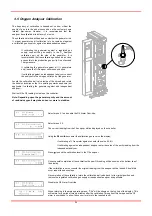
Locate the calibration ball valve inside of the shroud and rotate 
the handle clockwise so that it is pointing upwards as shown (not 
applicable if calibrating the generator against and independent 
analyser). 
 
Wait until the O2 reading is stable on the controller.  
 

Note: Depending upon the generator purity and the amount 
of residual oxygen it may take an hour or more to stabilise. 


Select menu 3.1 and enable the O2 Alarm Over-ride. 


Select menu 3.2  
 
The current reading from the 02 analyser will be displayed on the controller. 


Using the   and   keys enter the calibration gas level on the display.  
 

If calibrating a % Generator against air enter the value 20.9% 
 
If calibrating against an independent analyser enter the value of the purity reading from the 
independent analyser. 

 
Press   to send the calibration level to the O2 analyser. 


On successful completion of the calibration the new O2 reading will be shown on the bottom line of 
the display.  
 
If the calibration is not successful the original reading from the analyser will be loaded. Should this 
occur repeat the above steps. 
 
On completion of the calibration, return the calibration ball valve back to its original position and 
remove the regulated calibration gas supply or independent analyser as applicable. 
 
Disable the O2 Alarm Over-ride. 


When returning to the main operating menu, “CAL” will be shown on the top line of the display. This 
will remain for a period of twenty minutes after the calibration. Throughout this time period the O2 
alarm is overridden, to allow the sensor to return to the required level. 

Содержание Maxigas 104

Страница 1: ...104 120 SERVICE GUIDE ...

Страница 2: ......

Страница 3: ...ment Change 18 3 4 4 Outlet Flow valve replacement 19 3 4 5 Control Valve replacement 19 3 4 6 Inlet Valve Replacement 20 3 4 7 Outlet Valve Replacement 21 3 4 8 Equalisation Valve Replacement 22 3 4 9 Exhaust Valve Replacement 23 3 5 Oxygen Analyser Calibration 24 4 Oxygen Analyser 25 E1 Calibrate sensor 26 E2 Analogue output FSD 26 E3 Set 4 mA output 26 E4 Set 20 mA output 26 E5 Sensor simulatio...

Страница 4: ......

Страница 5: ...re that the equipment is depressurised and electrically isolated prior to carrying out any of the procedures specified within this manual Most accidents that occur during the operation and maintenance of machinery are the result of failure to observe basic safety rules and procedures Accidents can be avoided by recognising that any machinery is potentially hazardous domnick hunter can not anticipa...

Страница 6: ...odour Slightly lighter than air Ensure adequate ventilation Breathing 100 nitrogen will produce immediate unconsciousness and death due to lack of oxygen NON FLAMMABLE COMPRESSED GAS The following symbols are used within this user guide Highlights actions or procedures which if not performed correctly may lead to personal injury or death Highlights actions or procedures which if not performed corr...

Страница 7: ...5 and 145 261 Inlet Temperature o C o F 5 50 41 122 Port Connections Air Inlet G1 N2 Outlet to Buffer G1 N2 Inlet from Buffer G1 2 N2 Outlet G1 2 Supply Voltage V ac 50 60Hz 100 240 10 Power W 38 Ambient Temperature o C o F 5 50 41 122 Humidity 50 40 o C 80 MAX 31 o C IP Rating IP20 NEMA 1 Pollution Degree 2 Installation Category II Altitude m ft 2000 6562 Noise dB A 75 80 ...

Страница 8: ......

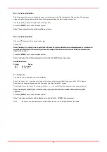
Страница 9: ...ntry to be added into the fault log Fault Codes C1 Pressure Start Inhibit P1 Inlet Pressure Fault P2 Pressure Sensor Fault E1 Power Failure Y1 O2 Alarm Y2 O2 Communication failure Y3 Incorrect cell selected Y4 O2 high out of range Y5 O2 zero drift error S1 Service due Menus 3 to 7 are all password protected This is designed to prevent unauthorised access to all configurable parameters The followin...

Страница 10: ...10 Menu Map ...

Страница 11: ...11 ...

Страница 12: ...xygen display settings 3 Equalising non equalising 1 1 0 1 0 Non Eq 1 Eq 4 Oxygen sensor 1 0 1 0 Digital 1 RS232 5 Service enable 1 0 1 0 off 1 on 6 Service due at 100 0 999900 0 7 Clear fault log 1 0 1 0 8 Pressure sensor fitted 1 0 1 0 Not fitted 1 Fitted 9 Pressure sensor units Bar PSI MPa Bar 10 Eco Pressure Hi Bar PSI MPa 0 1 4 1 20 10 0 Bar 11 Eco Pressure Lo Bar PSI MPa 0 1 4 19 9 9 5 Bar 1...

Страница 13: ... PSI Mpa 0 1 4 0 25 0 20 0 7 Test buttons 1 0 1 0 Menu 7 Service 4 Customisation Item Description Units Step Min Max Default 1 Inlet period S 1 10 600 See table 2 Exhaust period S 1 9 599 See table 3 Equilisation period S 0 5 0 5 5 See table 4 Inlet pressure delay S 1 0 600 60 5 Rapid start period S 1 10 600 40 6 Start clean up cycles 1 1 10 2 7 Pure start A cycles ppm 1 1 10 2 8 Pure start B cycl...

Страница 14: ......

Страница 15: ... System Check inlet air quality Generator Check for air leaks Generator Check pressure gauges during purging for excessive back pressure Generator Check condition of electrical supply cables and conduits Generator Check cyclic operation Generator Replace active exhaust silencers Recommended Service A Filtration Replace dust and control air filters Recommended Service B Generator Replace Calibrate ...

Страница 16: ...haust Silencer Kit 608620090 B Filter Service Filter Element Kit 020AR PPM O2 Cell Kit 606500002 C O2 Cell Service O2 Cell Kit 606500003 PPM Valve Overhaul Kit without equalisation valve 606500004 D Valve Service Valve Overhaul with equalisation valve 606500005 A E C D D D ...

Страница 17: ...own sequence The generator will complete the current cycle and then exhaust both beds Observe the column pressure gauges on the side on the generator to ensure that they read 0bar When the generator is completely depressurised it will revert to standby mode Disconnect the generator from the electrical supply at the supply disconnection switch Ensure that this switch is locked off to prevent accide...

Страница 18: ...sor 3 Ground 4 ve ppm vol sensor 5 ve ppm vol sensor Calibrate the sensor as detailed in section 4 7 Note PPM cells require the offset value to entered prior to calibrating 3 4 3 Dust Filter Element Change Close the buffer vessel outlet valve to isolate the housing and close the Nitrogen outlet valve De pressurise the buffer vessel filter by opening the drain valve on the base of the filter Observ...

Страница 19: ...est the assembly and re connect the solenoid plugs remembering to check for the correct orientation 3 4 5 Control Valve replacement The control valves are mounted on the back plate of the shroud as shown Make a note of the tubing and solenoid plug connections and remove them all Unscrew the four M5 screws holding the manifold onto the back plate and remove If only one valve from the block is to be...

Страница 20: ...he cylinders insert a 10mm spanner through the VSR plug hole onto the machined flat on the cylinder shaft With the cylinder shaft held securely loosen the M6 Hex head stem bolt that holds the discs onto the shafts Remove the cylinders from the inlet outlet plate by unscrewing the M6 socket head screws Replace the nose seal and fit the replacement cylinders to the plate Torque the bolts down to 20N...

Страница 21: ...the cylinders insert a 10mm spanner through the VSR plug hole onto the machined flat on the cylinder shaft With the cylinder shaft held securely loosen the M6 Hex head stem bolt that holds the discs onto the shafts Remove the cylinders from the inlet outlet plate by unscrewing the M6 socket head screws Replace the nose seal and fit the replacement cylinders to the plate Torque the bolts down to 20...

Страница 22: ...r shaft With the cylinder shaft held securely loosen the M6 Hex head stem bolt that holds the discs onto the shaft Remove the cylinder from the equalisation plate by unscrewing the M6 socket head screws Replace the nose seal and fit the replacement cylinder to the plate Torque the bolts down to 20Nm 15ft lb Assemble the valve discs onto the M6 x 25L stem bolts in the following order M6 anti vibrat...

Страница 23: ...onto the machined flat on the cylinder shaft With the cylinder shaft held securely loosen the M6 Binx nut that holds the discs onto the shaft Remove the cylinders from the assembly by unscrewing the M6 socket head screws 4 per cylinder Fit the replacement cylinder to the plate ensuring that the nose o ring is in place Torque the bolts down to 20Nm 15ft lb Extend the cylinder shafts and assemble th...

Страница 24: ...nalyser Wait until the O2 reading is stable on the controller Note Depending upon the generator purity and the amount of residual oxygen it may take an hour or more to stabilise Select menu 3 1 and enable the O2 Alarm Over ride Select menu 3 2 The current reading from the 02 analyser will be displayed on the controller Using the and keys enter the calibration gas level on the display If calibratin...

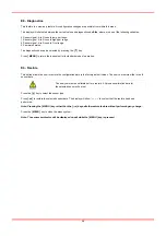
Страница 25: ...4 No connection The analyser has a 9 page menu system available to the end user This allows the following calibration and configuration activities to be performed Menu Function E 1 Calibrate Sensor E 2 Analogue output FSD E 3 Set 4 mA E 4 Set 20 mA E 5 Sensor simulation E 6 Set sensor type E 7 Zero sensor E 8 Diagnostics E 9 Factory default settings The menu system is accessed by pressing the MENU...

Страница 26: ...l for details E2 Analogue output FSD Using the and keys adjust the FSD to the required level Press Note Pressing the MENU key rather than the ENTER key exits the sensor FSD feature without any change Press the MENU key to close the menu system Note The Sensor FSD will be displayed on exit while the MENU key is pressed E3 Set 4 mA output Monitor the current sourced from the analogue output of the m...

Страница 27: ...tted to the analyser Press the MENU key to close the menu system Note The Sensor Type will be displayed on exit while the MENU key is pressed Available sensors Display Range O2 1 0 25 Volume O2 2 0 1000 ppm E7 Sensor zero The module can be zeroed by one of two methods Ensure the sensor is in a zero gas environment the sensor is best zeroed whilst being exposed to 100 nitrogen Disconnect the sensor...

Страница 28: ...its standard mode of operation E9 Restore This option allows the user to restore the configuration data to the factory default values The user can restore either or both sensor data The analyser must be calibrated after a restore All previous calibration data for the selected sensor will be lost Press the key to select the sensor type Press to restore the selected sensor data The display will show...

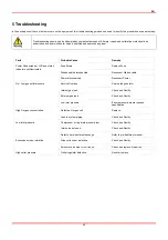
Страница 29: ...d Power disconnected Reconnect Power Service Overdue Service the generator Internal gas leak Check and Rectify External gas leak Check and Rectify No Low gas outlet pressure Low inlet pressure Ensure pressure meets required specification Defective Oxygen cell Replace High Oxygen concentration Leak in system piping Check and Rectify Compressor or ring main pressure low Check and Rectify Inlet valve...

Страница 30: ......

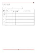
Страница 31: ...EN 31 6 Service Record Date of Commissioning Serviced By Service Hours Hours Shown Date Print Initials Comments Observations 4 000 8 000 16 000 20 000 24 000 28 000 32 000 36 000 40 000 ...

Страница 32: ......

Страница 33: ...EN 33 APPENDIX A SCHEMATICS ...

Страница 34: ......

Страница 35: ......

Страница 36: ... publication is for general information only and customers are requested to contact our Industrial Sales Department for detailed information and advice on a products suitability for specific applications All products are sold subject to the Company s standard conditions of sale Parker Hannifin ltd Dukesway Team Valley Trading Estate Gateshead Tyne and Wear England NE11 0PZ Tel 44 0 191 402 9000 Fa...

Отзывы: