background image

9.

Re-install mounting screws to refrigerator frame in

reverse sequence of steps B and C to attach door-

hinge assembly to refrigerator. DO NOT COM-

PLETELY TIGHTEN SCREWS.

h. CHECK THAT DOOR OPENS AND CLOSES

PROPERLY AND THAT LATCH ASSEMBLY

ENGAGES BEFORE TIGHTENING SCREWS.

NOTE: Re-tighten all screws securely after changing

the hinge position.

INSTRUCTIONS FOR MOUNTING

THE DOOR PANEL

The refrigerator is normally delivered without door panel.

Before starting the mounting work, check that the panel

dimensions are in compliance with those given in the

table and the instructions are read thoroughly.

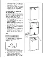
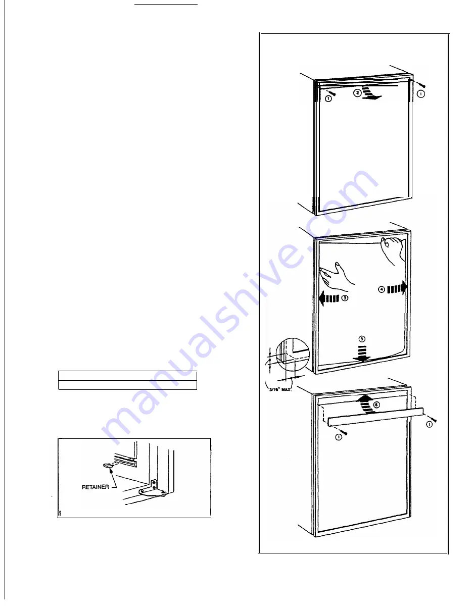
When mounting the panel, proceed as follows):

A.

B.

C.

D.

E.

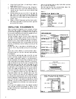
Remove the door de&ration strip (2) with its two

screws (1). The lower comers of the panel have to

be cut according to the sketch.

Insert one of the vertical edges of the panel into the

groove of the door frame (3).

Bend the panel gently so that the free side of the

panel can be slipped into the corresponding groove

of the door frame (4). Slide the panel down into the

groove of the bottom frame (5).

Between the upper edge of the panel and the door

frame there is now a gap which should be covered

by the decoration strip.

Put the decoration strip across the door so that the

gap is covered and push it upwards (6). The tabs on

the inside of the strip should fii in behind the flange

of the door frame. Secure the decoration strip by

means of the two screws removed in Step A (1).

Table 3

Panel Dimensions

Models S 1521, S


1531

21-19/32”x 36-1/16"

NOTE: Door panel thickness should not exceed 5/32”.

INSTRUCTIONS FOR REPLACING

CRISPER GLASS

FIG.

 15

1.

Remove the retainers (see FIG. 15) by prying out

from side of liner with


a flat blade screwdriver being

careful not


to damage the liner.

2. After removing the retainers slide new glass in place

and install new retainers supplied with kit.

NOTE: Retainers should only be removed for re-

placement of crisper glass as they are not reusable.

8

Содержание Silhouette S1521

Страница 1: ...installation adjustment alteration service or maintenance can cause injury or property damage Refer to this manual For assistance or additional information consult a qualified installer service agenc...

Страница 2: ...AUTO Mode Indicator Lamp E CHECK Indicator Lamp GAS Mode Only F Temperature indicator Lamps PROTECTION PLATE FIG 2 F LEGEND 3 WAY AMES Model 1 Main Power Button ON OFF 2 DC Mode Selector Button 3 AUT...

Страница 3: ...on An opening toward the out side at floor level in the refrigerator compartment must be provided for ventilation of heavier than air fuel gases The lower vent of the recommended kiis is provided with...

Страница 4: ...alled must be sealed Make sure that there is a complete seal between the front frame of the refrigerator and the top sides and bottom of the enclosure A length of sealing strip is applied to the rear...

Страница 5: ...ondenser and absorber tubes see FIG 6 must receive a continual supply of cooler air in order to main tain proper refrigerator cooling A recommended 0 clearance between the back of the refrigerator and...

Страница 6: ...3 Bend the panel gently so that the free side of the panel can be slipped into the corresponding groove of the door frame 4 Slide the panel down into the groove of the bottom frame 5 Between the upper...

Страница 7: ...be leveled only so it is comfortable to live in no noticeable sloping of floor or walls When the vehicle is moving the leveling is not critical as the rolling and pitching movment of the vehicle will...

Страница 8: ...TO SHUT OFF THE REFRIGERATOR The refrigerator may be shut off while in any mode of operation by pressing the main power ON OFF button to the UP OFF position This shuts off all DC power to the refriger...

Страница 9: ...mode indicator lamp A will be illuminated All other mode lamps will be off The DC mode overrides all other operating modes If one of the other operating modes is desired the DC selector button 2 must...

Страница 10: ...thermostat is set at its highest position It is a good idea to do this a few hours before the an ticipated need for ice but be sure to move back to nor mal setting usually about mid setting when the...

Страница 11: ...and the 12 volt wires 2 Remove the power module cover See FIG 1 3 Snap the fuse out of the fuse holder 4 Fit a new fuse in to the fuse holder 5 Replace the power module cover 1 2 A MAINTENANCE SERVICE...

Страница 12: ...th a brush Blow out bumerwith compressed air Before removing burner jet clean burner area of soot and scale that fell out of flue tube Remove the burner jet Soak the jet in wood alcohol and blow it ou...

Страница 13: ...flue tube see side 3 FIG 1 2 4 Burner dirty Clean See Section Maintenance ser vice item 2 Periodic Maintenance Paragraph E item 8 2 5 LP gas pressure low at burner Set main regulator so pressure does...

Страница 14: ......

Отзывы: