

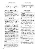


12 Volts DC Connection
All
refrigerator models require a 12 volt DC supply (even
though 2-way models are designed to operate on 120
volts AC and gas, a 12 volt DC control is required to main-
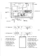
tain the automatic energy system). The DC lead connec-
tions are at terminals located at the rear of the
refrigerator. (see FIG. 1). One lead is marked positive (+)
and the other negative (-). Correct polarity must be ob-
served when connecting to the DC supply.
Do not use the chassis or vehicle frame as one of the
conductors. Connect two wires at the refrigerator and
route to the DC supply.
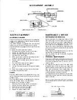
12 Volts DC Connection 3-way models
The distance the current must travel from the battery to
the refrigerator dictates the AWG wire size to be used.
Should the wire be too small for the distance, a voltage
drop will result.
The voltage drop affects the wattage output of the 12 volt
cartridge heater and resultant refrigerator performance.
Recommended wire sizes are shown below.
Maximum total conductor wire length in feet and meters.
The wires from the battery to the refrigerator must be of
large enough size to handle the load. The connections
must be clean, tight and free from corrosion. If not, a
resulting voltage drop will cause a decreased cooling
capacity.
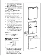
INSTALLING REFRIGERATOR IN
ENCLOSURE
NOTE: DO NOT install the appliance directly on car-
peting. Carpeting must be removed or
protected by a metal or wood panel beneath
the appliance which extends at least full
width and depth of the appliance.
CLEARANCES
Minimum clearances in inches to combustible materials
are: Top 0;
Side
0;
Bottom
0;
Rear
0.
The refrigerator must be installed in a substantial
enclosure and must be level. When installing the
refrigerator in the endosure, all areas within the recess
in which the refrigerator is installed must be sealed.
Make sure that there is a complete seal between the front
frame of the refrigerator and the top, sides and bottom
of the enclosure. A length of sealing strip is applied to
the rear surface of the front frame for this purpose. The
sealing should provide a complete isolation of the
appliance’s combustion system from thevehicle interior.
The refrigerator, designed for built-in installation, re-
quires opening dimensions as specified in Tablel.
Table 1
Refrigerator Cut-Out Openings (inches)
Model Height Width Depth
S 1521,S1531 43 1/4 23.5 24.0
After refrigerator is mounted in place (insuring a com-
bustion seal at the front mounting flange), the unit can
be secured by screws through the mounting flange and
hole(s) provided at floor level in the rear. Caps are
provided to cover the mounting flange screws.
Seal strips, provided with the refrigerator, must be in
position behind the mounting flange after the refrigerator
is installed in the wall enclosure. The seal must be con-
tinuos between the flange and the wall to assure com-
bustion seal. Care should be taken when installing or
removing the refrigeratorthat the strips are not disturbed
or damaged.(See FIG. 8).
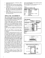
Lower Flange Installation
The lower flange is shipped as a loose part to prevent
damageduring shipment. The part is to be attached after
the refrigerator is set into the cut-out opening.
1. Install the lower flange by maneuvering it under and
behind the bottom hinge plate, as shown in FIG. 4
(the hinge will be located on either the right or left
side, depending on door swing preference).
2. Once the lower flange is slipped around the hinge,
the part will swing into place as shown in FIG. 5.
3. Secure the flange with screws provided.
FIG_
5
TESTING LP GAS SAFETY
SHUTOFF
The gas safety shutoff must be tested after the
refrigerator is connected to LP gas supply.
To test the gas safety shutoff, proceed as follows:
1. Start the refrigerator and switch to gas mode. (see
start up instructions).
5
Содержание Silhouette S1521
Страница 14: ......