6
Y
Y
Y
Y
Y
English
L-2347K Installation
Before You Start
1. Read installation and operating instructions carefully
before attempting to install and operate your air condition-
ing unit.
2. The manufacturer will not be liable for any damages,
injury, or death incurred due to failure to follow the
instructions.
3. Installations must always comply with the National
Electrical Code, and any state/local codes or regulations.
4. Only a qualified service technician must service this unit.
Any attempt to service the unit otherwise may void the
warranty.
5. Make sure that you have the required parts and tools to
complete the job, as this will help keep the installation
time to a minimum.
Warning
• Improper installation could damage equipment,
endanger life, cause serious injury, or property
damage.
• If you have any doubts that you cannot complete this
installation safely and as the directions state, find a
qualified technician to do it for you.
• Make sure that power is turned off at the source
before making any connections. Failure to do so could
cause injury or death.
Required Additional Parts
If you have received only the unit, and not the complete kit,
you will need to supply some additional parts for installation,
such as ductwork, grill(s), drain fitting, ½" X ½" wire mesh,
½" thick weather stripping, two 5½" hose clamps, one 1-1/8"
hose clamp, wiring, ¼" nuts and bolts, and 5/8" dia. drain
hose. The duct should be 5" diameter minimum. The two
large hose clamps can be used to secure the duct to the unit
and the grill to the duct. The drain fitting should be 3/8" MPT
to a 5/8" hose barb. The wire mesh will be used to put over
the holes that will be cut through the sleeper floor to assure
that small animals and other uninvited guests do not get into
the sleeper. Use the weather stripping to seal the area
between the AC unit and the floor of the sleeper. The wiring
sizes are noted in the SPECIFICATIONS section.
Warning
The seal between the unit and the floor is extremely
important. This seal is intended to prevent deadly
gasses from entering the living space!
Self-Contained HVAC System for Truck Sleepers • Installation
Required Tools
Tools that will aid in installation: drill and bits, 1-5/8" hole saw,
reciprocating saw with metal blades, Phillips and straight
blade screwdrivers, measuring tape, and Teflon tape or
equivalent.
Choosing The Correct Place
For Your Unit
The self-contained unit is easier to install than the remote
system, but it will take up more room under the bunk. A
remote system consists of two major components, the
condenser and the evaporator, while the self-containted unit
stands alone. The remote condenser is installed outside the
cab; the remote evaporator is installed inside the sleeper.
Generally speaking, the self-contained unit is installed with
the long dimension lengthways of the sleeper. This would put
the evaporator intake close to the bunk bulkhead. The
evaporator intake must be have a minimum open area equal
to the size of the coil face. For example, a coil that is 10" x
9½" would require 95 in
2
of open return to the unit. The
evaporator discharge can then be ducted to wherever best
suits the truck arrangement.
Mounting The Unit
Installing the Self-Contained Unit
Decide where you are going to install the unit. Using the
template provided, mark off the required holes (condenser
inlet and outlet, mounting holes, and drain hole), and check
for interference between the holes and the structural
members that are under the sleeper floor. After you have
checked, cut the holes in the floor of the sleeper. Use the
wire mesh to cover each hole so that small animals cannot
get in. Take the weather stripping, and make a frame around
the holes on the unit. Install the MPT drain fitting into the
drain hole using the Teflon tape. Line the unit up over the
holes, and set squarely onto the floor.
NOTE:
Take care not to crush or break the drain fitting while
moving the unit around. Use the four bolts, washer and nuts
to secure the unit to the floor.
NOTE:
The manufacturer is not responsible for mounting, nor
is responsible for failure of such mounting and subsequent
unit damage. The unit will need to be positioned so that
electrical and refrigerant connections can be accessed, and
so that cleaning of the condenser coil may be performed.
The unit should be securely fastened to the mounting frame
with ¼" bolts and lock nuts.
Содержание Kohler 7APU
Страница 2: ......
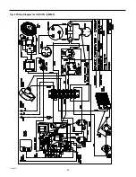
Страница 20: ...20 L 2347K Fig 2 Wiring Diagram for ASCDX14 080359 ...
Страница 21: ...21 L 2347K Fig 3 Wiring Diagram for ASCDX10 080343 ...
Страница 22: ...22 L 2347K Fig 4 Wiring Diagram for ASCDX7 080356 ...
Страница 23: ...23 L 2347K Fig 5 Wiring Diagram for ASCF7 080344 ...


