7
07.10.15 en / 477
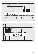
Application Examples
Emergency stop, 2-channel, 4 start inputs, contact reinforcement; setting: 0, 4 or 8
L+
L -
A1+
A2-
Y1
X11
Y2
S12
S11
S13
S14
X12
(-)
(-)
13
23
33
34
24
14
58
48
K1
K2
M9059_a
X11
T4
T3
T2
T1
T1
T2
T3
T4
X12
K3
K4
K3
K4
emergency stop
waiting for start,
error
error indication,
enabling active
machine enabling
BH5911
Technical Data
Nominal voltage U
N
:
DC 24 V
Voltage range:
with max. 5% residual ripple:
0.85 ... 1.15 U
N
Nominal consumption
BH 5911:
max. 140 mA
(no load on semiconductor outputs)
Input
Control voltage on
X11, X12, 48, 58:
DC 23 V at U
N
Control voltage on
S11, S12, S13, S14,
T1, T2, T3, T4:
4.5 mA each at U
N
max. wire length to
sensors with contacts:
100 m
Minimum voltage at
terminals S12, S14
T1, T2, T3, T4:
DC 16 V
Short-circuit protection
of the modules:
Internally with PTC
Output
Contacts
BH 5911.03:
3 NO contacts
BH 5911.22:
2 NO contacts, 1 NC contact
(The NC contact must not be used as
a safety output!)
Contact type:
Relay, forcibly guided
Typ. make time with U
N
:
Control unit BH 5911
Manual start
Auto start
First start
Restart
Emergency stop
max. 75 ms
max. 1 s
max. 90 ms
Break time (reaction time):
Control unit BH 5911
Emergency stop
max. 27 ms
Fault clearing
in the feed back loop:
max. 600 ms
Output nominal voltage:
AC 250 V
DC: see limit curve for arc-free operation
Switching of small loads:
≥
100 mV
Thermal current I
th
:
max. 5 A (see quadratic total current
limit curve)
Switching capacity
to AC 15
NO contact:
3 A / AC 230 V
IEC/EN 60 947-5-1
NC contact:
2 A / AC 230 V
IEC/EN 60 947-5-1
to DC 13:
DC8 A / DC 24 V
at 0.1 Hz
IEC/EN 60 947-5-1
Contact life
acc. to AC 15 with 2 A, AC 230V:10
5
switching cycles IEC/EN 60 947-5-1
Permissible switching
frequency:
max. 1 200 switching cycles / h
Short circuit strenght
max. fuse rating
6 A gL
IEC/EN 60 947-5-1
Line circuit breaker
C 8 A
Mechanical life:
10 x 10
6
operating cycles
Semiconductor Outputs
Output (terminal 48 and 58):
Transistor outputs, plus-connected
Output nominal voltage:
DC 24 V, max. 100 mA constant
current, max. 400 mA for 0,5 s internal
short circuit, overtemperature and
overload protection
General Data
Operatinng mode:
Continuous
Temperature range:
±
0 ... + 50 °C
At an operating temperature of 50 °C
the modules must be mounted with
a distance of 3 - 5 mm.
Clearance and creepage
distances
rated impulse voltage /
pollution degree:
4 kV / 2 (basis insulation) IEC 60 664-1
EMC:
IEC/EN 61 326-3-1, IEC/EN 62 061
Radio interference suppression: Limit value class A
EN 55011
Remark: This device is designed for industrial ambient conditions.
When used in other environment, it is possible that wire bound or
radiated interference occurs.
Degree of protection
Housing:
IP 20
IEC/EN 60 529
Terminals:
IP 20
IEC/EN 60 529
Housing:
Thermoplast with V0 behavior
according to UL Subject 94


