


User Information
Load-bearing tower Staxo 100
System description
23
999804302 - 02/2018
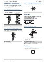
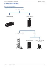
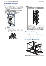
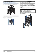
Height adjustment
▪
The 3 different heights of frame 0.90
m, 1.20
m and
1.80
m enable coarse adjustment to within 30
cm.
▪
Fine adjustment, down to the last millimetre, is done
using the various head and base units.
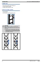
System dimensions
on multi-storey towers
Regarding Table A ‘Height ranges and materials
schedule’, use the version of this table given in the
chapter for the usage situation concerned.
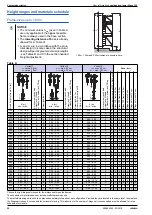
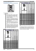
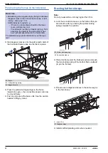
Table B: Head zone
Values in cm
Min. values with no formwork-striking play
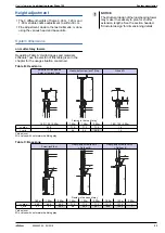
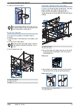
Table C: Base zone
Values in cm
Min. values with no formwork-striking play
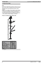
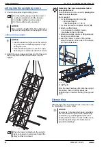
NOTICE
The structural design of the load-bearing tower
may make it necessary to plan for shorter
extension lengths. See the section headed
'Structural design' for dimensioning details.
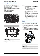
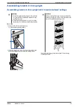
Screw jack U-head and
4-way screw-jack head
Heavy-duty screw jack 70 top
U-head D
Frames in the top 'storey'
1.80 / 1.20 / 0.90m
1.80m
1.20m
0.90m
1.80 / 1.20 / 0.90m
L
K
max.
45.8
71.2
71.2
71.2
1.6
L
K
min.
7.8
8.4
8.4
24.9
1.6
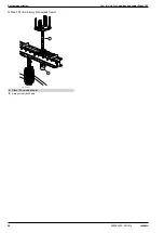
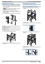
Screw-jack foot
Heavy-duty screw jack 70
+ Split nut B
Heavy-duty screw jack 130
+ Split nut B
Frames in the base 'storey'
1.80m
1.20m
0.90m
1.80m
1.20m
0.90m
1.80m
1.20m
0.90m
L
F
max.
46.2
46.2
46.2
71.2
71.2
71.2
131.2
131.2
--
L
F
min.
8.2
8.2
26.3
8.8
28.2
58.1
40.0
100.0
--
98003-219-04
L
K
98003-237-01
L
K
98003-236-01
L
K
98003-219-03
L
F
98003-236-02
L
F
98003-236-03
L
F


