DFL 8 B SK / SK X / SK V / SK X V
Environmental testing
IEC 60068
dry heat
IEC 60068-2-2
damp heat
constant
IEC 60068-2-78
cyclic
IEC 60068-2-30
Cross sections
solid
1 x (4 mm² – 16 mm²); 2 x (4 mm² – 16 mm²)
stranded
1 x (25 mm² – 185 mm²); 2 x (25 mm² – 70 mm²)
Tightening torque
14 Nm
Endurance
mechanical
> 2,000 cycles
electrical
> 2,000 cycles
Design
requirements
Overload
tripping
VDE 0660 / EN 60947-2
Residual
current
tripping
VDE 0660 / EN 60947-2 Appendix B
Electromagnetic
compatibility
EN 60947-2 Appendix J
Weight
approx. 5,600 g
1)
DIN VDE 0636, IEC 60269
Auxiliary switch
Load rating
AC-15: 230 V / 6 A; 400 V / 4 A; 500 V / 2 A
DC-13: 24 V / 3 A; 110 V / 0.8 A; 220 V / 0.3 A
Rated operating voltage U
e
230/400 V AC
Rated impulse withstand
voltage U
imp
6 kV
Rated insulation voltage Ui
500 V
Cross-sections solid and
flexible with ferrules
1 x (0.75 mm² – 2.5 mm²); 2 x (0.75 mm² – 1.5 mm²)
Characteristics
1000
1
10
100
1000
10000
100000
100
10000
10
Frequenz / Frequenzy in Hz
Fehlerstro
m
/
R
esidual
current
in
mA
DF L 8 B S K / 30 mA
Auslösestromfrequenzgang / Tripping current frequenzy response
1000
1
10
100
1000
10000
100000
100
10000
10
Frequenz / Frequenzy in Hz
Fehlerstro
m
/
R
esidual
current
in
mA
DF L 8 B SK / 300 mA
Auslösestromfrequenzgang / Tripping current frequenzy response
1000
1
10
100
1000
10000
100000
100
10000
10
Frequenz / Frequenzy in Hz
Fehlerstro
m
/
R
esidual
current
in
mA
DF L 8 B S K / 500 mA
Auslösestromfrequenzgang / Tripping current frequenzy response
1000
1
10
100
1000
10000
100000
100
10000
10
Frequenz / Frequenzy in Hz
Fehlerstro
m
/
R
esidual
current
in
mA
DF L 8 B S K / 1000 mA
Auslösestromfrequenzgang / Tripping current frequenzy response
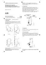
Application instructions and warnings
The following notes and warnings must be observed in order to ensure safe operation:
1. Installation may only be carried out by an authorised specialist, who is familiar
with the relevant national installation regulations.
2. Without an additional protective housing, the circuit-breaker with residual cur
rent trip may only be stored and operated in a dry, low-dust environment. An ag
gressive atmosphere must also be avoided.
3. The user must be made aware of repeat testing using the button T.
4. Using surge current strength CBRs cannot absolutely guarantee to rule out trips
due to leakage currents caused by surge voltage. In cases where an interruption of
the power supply may lead to potential dangers for humans and animals or dam
age to property, residual current protection should be implemented by means of
increased surge current strength, selective CBRs and upstream surge arresters. In
specific cases, the switching status should be monitored by means of an auxiliary
contactor at the circuit-breaker and an appropriate signalling device.
Guarantee
All professionally installed, unaltered devices are covered by warranty during the
statutory guarantee period from the day of purchase by the end user. The guaran
tee is not applicable to damage incurred during transport or caused by short-circuit,
overloading or improper use. In the event of defects in workmanship or material,
which are discovered within the guarantee period, the company will provide a repair
or replacement free of charge. The guarantee will be rendered null and void if the
device is opened without authorization.
Technical Data
DFL 8 B SK / SK X / SK V / SK X V
Rated current In
100 A
125 A
160 A
200 A
250 A
Rated residual
current I
�n
standard
0.03 A
series X
adjustable: 0.3 A, 0.5 A, 1.0 A
Detection range of residual
current
0 – 100 kHz, 50 or 60 Hz
Rated operat
ing voltage Ue
standard
230/400 V AC
series V
290/500 V AC
Rated frequency
50 Hz or 60 Hz
min.
operating
voltage
for detec
tion of
residual
currents
Type A/AC
0 V (mains independent)
for detec
tion of
residual
currents
Type B
50 V AC
Internal consumption
max. 2.5 – 3 W
operating
range of test
circuit
standard
50 V AC – 400 V AC
series V
50 V AC – 500 V AC
number of poles
four-pole
Dissipation power P
v
(typ.)
35 W
43 W
55 W
72 W
85 W
Short-circuit fuse
1)
250 A/gG
Response
times
standard
1 x I�n ≤ 300 ms; 5 x I�n ≤ 40 ms
series X
Range l = 60 – 120 ms
Range ll = 150 – 250 ms
Range lll = 300 – 420 ms
Range llll = 450 – 600 ms
Non-response
lag time
standard
undelayed
series X
Range l = < 60 ms
Range ll = < 150 ms
Range lll = < 300 ms
Range llll = < 450 ms
Rated shortcircuit discon
necting capacity limit I
cu
50 kA at 400/415 V AC
Rated operation short-
circuit disconnecting
capacity I
cs
50 kA at 400/415 V AC
Rated residual current
shortcircuit disconnecting
capacity I�m
50 kA at 400/415 V AC
Surge current strength
Proof of the resistance of CBRs to unintended tripping
from surge currents resulting from surge voltages
EN 60947-2:2003 (B.8.6)
Shock resistance
20 g / 20 ms duration (IEC 60068-2-27)
Vibration resistance
1.0 g (f = 2 – 100 Hz) (IEC 60068-2-6)
Type of protection
IP 20
Installation position
vertical or tilted by 90°
Supply side
bottom
Ambient temperature
-25 °C to +70 °C
1)
DIN VDE 0636, IEC 60269
Installation and Operating Manual
for circuit-breakers with residual current trip
of series DFL 8 B SK
Electrical connection
Guide all active conductors (outer cables L1, L2, L3 and the neutral conductor MP/N)
through the switch. The energy flow direction must be observed, i. e. the mains or
consumer unit has to be connected to the lower terminal block. Scrape and grease
aluminium conductors immediately before connection.
Function and area of application
The devices of the DFL 8 B series are circuit-breakers with residual current trip sensi
tive to all current types for the detection of residual currents of type B. They consist
of a section independent of the mains voltage for the detection of sinusoidal AC and
pulsing DC residual currents with the rated frequency 50 Hz or 60 Hz and a section de
pendent on the mains voltage for the detection of residual currents in the frequency
range 0 Hz to 100 kHz.
The devices are intended for use in single and multiple phase AC networks. They are
not intended for use in DC networks.
In order to ensure protection across the total frequency range covered in the event
of indirect contact with a maximum contact voltage of 50 V or 25 V respectively, the
earth resistance must be in accordance with the table given below.
Series
maximum touch voltage 25 V
maximum touch voltage 50 V
DFL 8 B SK
8.3 Ω
16.6 Ω
For frequencies > 1 kHz the tripping current for the DFL 8 B SK is up to approx 3 A.
This ensures its insensitivity to high leakage currents in the upper frequency range.
Testing and functional check
The testing of all safety measures on commissioning must be carried out according
to the information in the valid national installation regulations. An insulation test of
the user equipment is to be carried out in accordance with DIN EN 61557-2. This may
only be done when the device is switched off. Insulation testing when the device is
switched on or insulation testing on the input side may lead to incorrect measured
values. A functional inspection of the circuit-breaker with residual current trip itself
is possible with connected mains voltage by pressing the test button T and, as in com
mercial use (BGV A3), should be carried out at least every six months in the case of
stationary systems and should be repeated every working day in the case of non-
stationary systems.
The green LED signals that the internal operating voltage is sufficient for AC-DC sen
sitive residual current detection (residual currents of type AC, A and B). If the LED
does not illuminate, then only tripping via type AC and A residual currents is still
guaranteed. The internal supply of the device is via the bottom terminals. At least
two arbitrary conductors must conduct AC voltage of greater than 50 V in order to
guarantee AC-DC sensitive residual current detection.
Important information on operation with electronic equipment
(such as frequency converters, inverters etc.)
1. Electronic equipment and its associated EMC protective provisions, such as e. g.
integrated or in series-connected EMC filters, as well as shielded cables, can give
rise to high capacitive leakage currents.
2. The maximum number of items of electronic equipment connected downstream
of the device is based on the level of leakage currents that occur. Excessive leak
age currents may lead to undesired tripping in spite of the tripping current fre
quency response of the device. Relevant information concerning the discharge
currents that are produced can be requested from the manufacturers of the elec
tronic equipment.
3. During operation with frequency converters long, shielded motor cables may lead
to high discharge currents in the event of the controller release of the frequency
converter, which lead to undesired tripping. If necessary, a sinusoidal output filter
should then be used directly behind the frequency converter (before the shielded
motor cable).
4. According to the instructions, a conventional 3-conductor EMC filter should only
be connected in series with the relevant electronic equipment. So that the filter ef
fect is not impaired, under no circumstances should further single-phase consum
ers such as incandescent bulbs be connected on the output side of the EMC filter.
5. As a rule, different clock frequencies (chopper) can be selected in the case of elec
tronic equipment. In an unfavourable case, the clock frequency may lead to a ten
dency to oscillation in an upstream EMC filter and therefore to greatly increased
leakage currents, which then result in a tripping of the device. In this case, the
clock frequency must be changed.
Doepke
3930202
|
11/2013
|
Doepke Schaltgeräte GmbH, Stellmacherstraße 11, D-26506 Norden
DE EN