DTK-2MHTP (2-Pair Modular Hybrid Telco Protector)
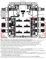
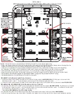
1. Connect the tele-communication circuit(s) from the field to the side marked
UN-PROTECTED
. The first pair is connected to the
terminals marked 1+ and 1- . If a second pair is used, connect to the terminals marked 2+ and 2- .
2. Connect the tele-communication circuits(s) for the alarm panel supply wiring, for the dialer circuit, to the side marked
PROTECTED
.
1. Connect the SLC, IDC, PIV
*
or NAC
*
loop circuit wiring from the field to the side marked
UN-PROTECTED
. The first pair is connected
to the terminals marked 3+ and 3- . If a second pair is used, connect to the terminals marked 4+ and 4- . If additional circuits need
to be protected, continue with 5+, 5- and 6+, 6- through 12+, 12-.
* Do not use DTK-2MHLPxxF for PIV or NAC circuits.
2. Connect the SLC, IDC, PIV or NAC loop circuit wiring, for the alarm panel inputs, to the side marked
PROTECTED
.
3. After all connections have been made and no hazards exist, replace cover, and proceed to the surge module installation sections.
DTK-2MHLPXXB, DTK-2MHLPXXF (2-Pair Modular Hybrid Line Protector)
Notes:
Connect this device in series between the field wiring and the control panel supply wiring.
• These Low Voltage protection circuits are equipped with a removable plug and header assembly. Simply remove the plug from the
header, terminate your wires, then replace the plug making sure it seats and snaps into place.
• There are up to 6 positions for surge modules available for protection of any combination of Dialer Circuit, SLC (Signaling),
IDC (Initiating), PIV (Valve) or NAC (Notifying) circuits. Each module will protect 2 pairs or circuits of the same voltage.
• All modules have been factory pre-wired for ground. It is not necessary to make any additional ground connections.
• Allow for sufficient reaction time by providing a minimum of 3 wire feet between the DTK-120X12 and the alarm panel inputs.
• Use separate conduit feeds to isolate the unprotected “INPUT” wiring from the protected “OUTPUT” wiring.
• Use appropriately sized conduit fittings and conduit (not included).
-FIELD WIRING
-INPUT*
-UNPROTECTED
-SUPPLY
-OUTPUT*
-PROTECTED
#30-12 AWG
DITEK
Surge Protection
R
1-2
3-4
5-6
7-8
9-10
11-12
EARTH
NEUT
LINE IN
EARTH
NEUT
LINE OUT
2-
2+
1-
1+
4-
4+
3-
3+
6-
6+
5-
5+
12
-12
+
11
-1
1+
10
-
10
+
9-
9+
8-
8+
7-
7+
2-
2+
1-
1+
4-
4+
3-
3+
6-
6+
5-
5+
12
-1
2+
11
-11
+
10
-
10
+
9-
9+
8-
8+
7-
7+
NC C NO
LOAD
LINE
UN-PROTECTED
PROTECTED
IF NOT USING
THE DRY CONTACT
CIRCUIT, THIS
1/2” CONDUIT CAN
BE USED FOR THE
LOW VOLTAGE
LOOP CIRCUITS
DTK-120X12
(Wiring Diagram-Low Voltage Surge Modules Without Dry Contact Circuit)


