background image

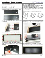
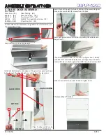
1. BASE ASSEMBLY:

Parts needed:

Panel B   (X2)              Cam Screw  (X16)

Panel C   (X2)              Cam Lock    (X16)

Panel D   (X1)              Glide Foot  (X4)

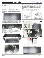
How to join 2 boards with CAM lock:

(a) Insert cam post into flat surface of a board. Fit the hole in 

the edge of the joining board over the cam post.

(b) Each cam lock has an open sec�on at the back. Insert the 

cam lock into the cam lock hole. Be sure the opening fits the 

head of the cam post.

(c) Use a screw driver to turn the cam lock clockwise so it 

locks onto the head of the cam post. Do not over �ghten.

Insert (4) cam screws into each of two Panel (C) as shown: 

A�ach Panel (B) with Panel (C) by inser�ng Cam Screws into 

Cam Lock holes.

Insert (4) Cam Lock into cam lock holes on Panel (B), use a 

phillips screw driver to rotate cam locks clockwise to secure 

cam screws.

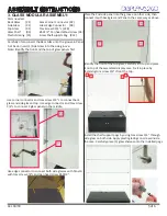
Connect (2) Panel (B) and (2) Panel (C) as shown. Be sure the 

edges with pre-drilled holes face the same side.

Use rubber mallet to hammer (4) feet into the bo�om side (no 

pre-drilled hole).

C

C

B

B

Insert (8) cam screws into Panel D.

A�ach the assembly of Panel B and Panel C to Panel D by 

inser�ng cam screws into the cam screw holes. Secure Panel D 

by using cam locks. 

3 of 6

ASSEMBLY INSTRUCTIONS

Ver. 04/18

Содержание FRCHVWBK

Страница 1: ... or product damage due to mishandling incorrect mounting incorrect assembly or incorrect use of this product 2 people are needed for assembly 3 people are recommended if you have any questions regarding our products please contact D2G customer service Phillips Screwdriver Rubber Mallet T20 Torx Screwdriver ASSEMBLY INSTRUCTIONS HALF VISION WALL CASE FRCHVWBK 1 of 6 Ver 04 18 TOOLS NEEDED ...

Страница 2: ...s X2 Glass Shelf X3 Front Front Top Top Cam Screw X36 Cam Lock X36 Glide Foot X4 Glass Corner Connector X2 Glass Edge Connector X8 Door Knob X2 Door Hinge X4 Wood Screw X24 Torx Screw X3 4 L X28 Torx Screw X1 2 L X2 6X1 2 Pan Head Wood Screw X6 HWI16 4 X1 HWI8 4 X1 HWI17 4 X1 NE09034 4 X2 Glass Door Pull X2 Glass Top Guide X4 Glass Shelf Peg X12 Glass Glazing X4 Plastic Glazing X16 2 of 6 ASSEMBLY...

Страница 3: ...e cam post Do not over ghten Insert 4 cam screws into each of two Panel C as shown A ach Panel B with Panel C by inser ng Cam Screws into Cam Lock holes Insert 4 Cam Lock into cam lock holes on Panel B use a phillips screw driver to rotate cam locks clockwise to secure cam screws Connect 2 Panel B and 2 Panel C as shown Be sure the edges with pre drilled holes face the same side Use rubber mallet ...

Страница 4: ...ge of the door b Drive wood screws through screw holes in the flange to fix the hinge cup Secure the other hinge cup in the 2nd bored hole in door c A ach the door with hinges assembled with Panel F Align holes in the hinge plate with pre drilled holes in Panel F Drive wood screws into pre drilled holes to fix the door panel A ach door knob to Door Panel H on both doors 1 2 3 4 Insert 8 cam screws in...

Страница 5: ...or to connect both side glasses with Panel A with torx screw 3 4 L and pan head screw 6X1 2 Iden fy the front of the top glass carefully li it up and place it on top of the assembled display case Fix it in place by fastening torx screw 3 4 L front the top Parts needed Back Glass X1 Glass Corner Connector X2 Side Glass X2 Glass Edge Connector X8 Top Glass X1 Torx Screw X3 4 L X28 Glass Shelf X3 6X1...

Страница 6: ... guide rail Then carefully place HWI17 4 onto the top of glass doors Slowly push HWI 17 4 toward the display case and align the pre drilled holes with holes in the top glass Fix HWI17 4 with torx screw X1 2 Adhere door pull at the proper loca on on glass doors The assembly is finished Parts needed Glass Door X2 Glass Glazing X4 HWI16 4 X1 Glass Top Guide X4 HWI17 4 X1 Torx Screw X1 2 L X2 HWI8 4 X1...

Отзывы: