7
Unpacking & Assembly
Remove Mower Components from Crate
Open container and remove the mower seat assembly, motion
control levers, and all packing materials. Disassemble the front
side of the crate and push the mower onto a stable, flat surface.
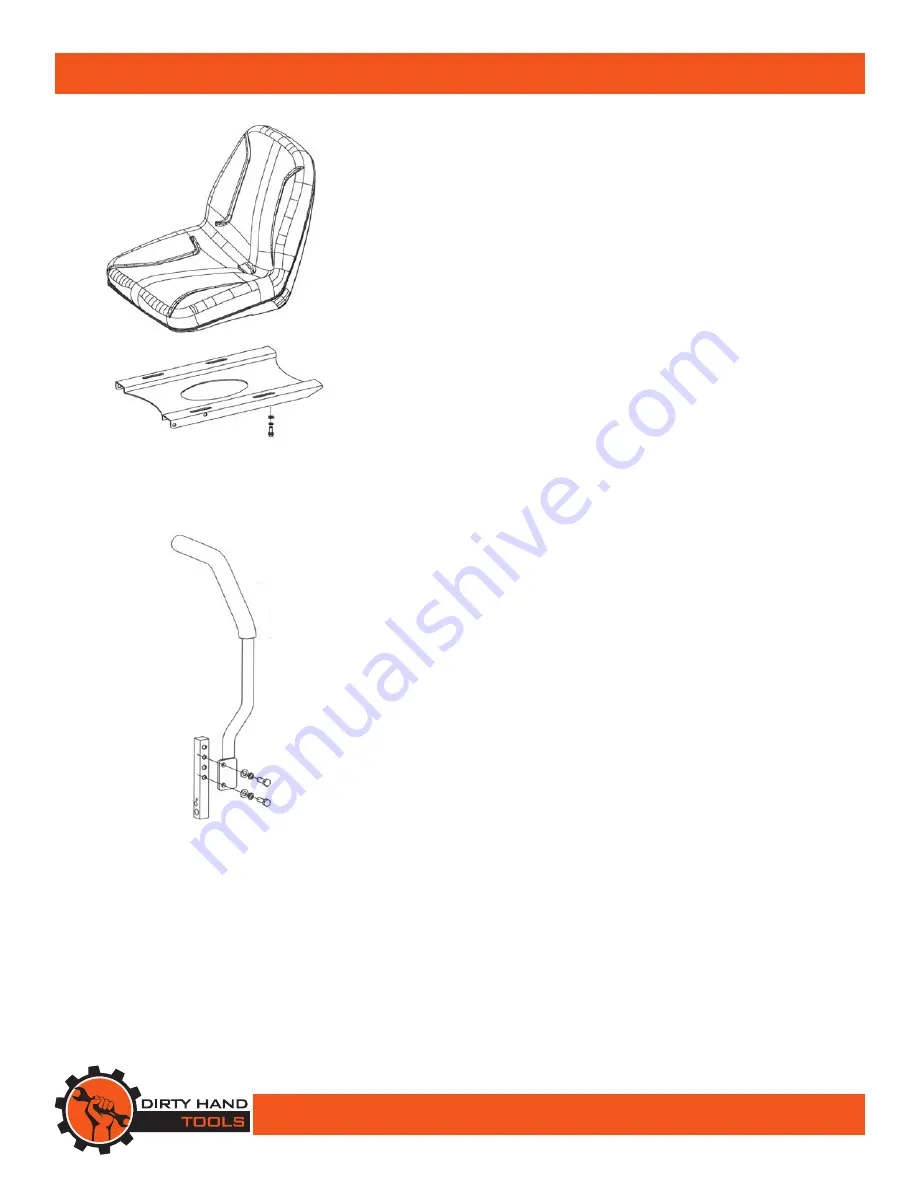
Attaching the Seat
Remove the seat assembly from the crate and four hex bolts,
four flat washers, and four spring washers from the hardware
included. Install four bolts through flat washers, spring washers,
and into the four holes in the seat bracket and thread them into
the four threaded holes in the bottom of the seat and tighten.
Attaching the Motion Control Levers
Remove the control levers from the crate and four M8×25 bolts,
four 8mm flat washers, and four 8mm spring washers from the
hardware included.
1. Place the right control lever to the outside of the control arm
shaft, insert the bolts into the holes with flat washers and
spring washers and tighten them (see Figure 2).
2. Install the left control lever in the same way.
NOTE: There are two lever height options available. Place the
levers in the first and the third hole (from the top) to increase
height of the levers or in the first and the third hole (from the
bottom) to decrease the height of the levers.
3. If the levers do not align with each other, when in the neutral
position, loosen the hardware and make the appropriate
adjustment by sliding the lever forward or backward until
properly aligned and tighten hardware.
4. If the ends of the levers hit against each other while in the
drive position, make adjustments by moving the levers outward
to the neutral lock position and carefully bending them
outward. Move them back to the drive position and check for
clearance, repeat if necessary.
Figure 2
Figure 1


