background image

7

7

© 2005 Directed Electronics, all rights reserved

N9405T  11-05

EExxaam

mp

pllee  SSeen

nsso

orr  P

Pllaacceem

meen

ntt  CCaallccu

ullaattiio

on

n::

1. Measure the mounting distance between the

proposed locations for sensor A and sensor D.

For this example (not to be used for your

vehicle) let’s say that measures 48”.

2. Then 0.3L is 0.3 X 48” = 14.4” 

and 0.4L is 0.4 X 48” = 19.2”

3. Hence, the distance that sensor B is from

sensor A is 14.4 inches, and the distance that

sendor C is from sensor D is 14.4 inches. The

distance between sensor B and C will be

19.2”.

N

NO

OTTEE:: These distances are approximate as mounting

locations have to be selected based on clearance behind
the bumper and any obstructions or bumper curvatures
on the surface of the bumper.

4. Drill the holes in the bumper as indicated in

the diagrams above and install the sensors.

Sensors A and D should N

NO

OTT be mounted on

the curve of the bumper.

N

No

ottee:: Before drilling any holes ensure the the area

behind is clear of any electrical, hydraulic, or support
members, etc.

N

No

ottee:: Wiring is shown and described is for a positive

reverse indicator system.

The ECU is water resistant, however, it is recom-

mended that the module be mounted in the trunk

compartment or for a truck in as much of a pro-

tected area as possible.

1. Use the 3-sheet metal screws to mount the

module.

2. Connect the white wire to reversing light(+)

Mount ECU in trunk
            or
for a truck in as much
of a protected
area as possible 

Connect the white wire

to reversing light(+)

sensor A

sensor B

sensor C

sensor D

 reversing lingt(+)

GND

white

black

ECU

EECCU

U  IInnssttaallllaattiioonn

UP

UP

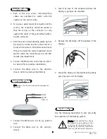
2. Install the sensor vertically,
the "up" sign must be on
upside.

1. Verify that the size of the 
supplied hole saw (18.5mm) 
is compatible to the diameter 
of the sensor by first drilling 
a test hole in a scrap piece of 
wood.

Содержание Valet 9405T

Страница 1: ...e This equipment has been tested and found to comply with the limits for a Class B digital device pur suant to part 15 of the FCC Rules These limits are designed to provide reasonable protection against harmful interference in a residential installation This equipment generates uses and can radiate radio fre quency energy and if not installed and used in accordance with the instructions may cause ...

Страница 2: ...e sensors when the reversing gear is engaged see Self Test Function and then the system starts sensing objects to the rear of your vehicle a The object distance is greater than 8 5Ft Zone 1 Green LED of display will flash b The object distance is 8 4 1Ft The display will show the distance by the digital number displayed and show the object s location in the Matrix LED Display c When the object dis...

Страница 3: ...top left of the display has three settings This switch has the following options z Beeps only low volume zz Beeps with voice low volume zzz Beeps with voice high volume D Di ig gi it ta al l M Ma at tr ri ix x L LE ED D D Di is sp pl la ay y Volume switch 1Ft Zone 5 Red LED 1 0 1 9Ft Zone 4 Red LED 2 0 2 8Ft Zone 3 Orange LED 2 9 4 8Ft Zone 2 Orange LED 4 9 8 4Ft Zone 1 Green LED ...

Страница 4: ...ow at less than 1 foot from the object If the volume switch is on a voice support position the distance and stop command will also be announced as you back up D Di ig gi it ta al l M Ma at tr ri ix x N Nu um me er ri ic c D Di is sp pl la ay y The digital number on display will show every 0 1M change of distance Audio warning Distance on display LED matrix display Zone 1 Zone 2 Zone 3 Zone 4 Zone ...

Страница 5: ...ult is a false reading The back up system only activates when the vehicle is placed in reverse gear When placed in reverse gear the system first does a diagnostic check to ensure the system is fully functional and reports any sensor malfunctions within the back up system If all the sensors are normal the system will beep once and the LED display will flash once If there is any malfunction with the...

Страница 6: ...ration 0 0 3L 0 4L 0 3L 5 8 inches 5 8 inches 1 foot 8 inches 2 feet 3 inches S Se en ns so or r I In ns st ta al ll la at ti io on n 6 6 2005 Directed Electronics all rights reserved N9405T 11 05 I In ns st ta alllla at tiio on n N No ot te e Before installing system let the components of the exhaust system cool down This will make the installation safer and preclude heat damage to the back up se...

Страница 7: ... and install the sensors Sensors A and D should N NO OT T be mounted on the curve of the bumper N No ot te e Before drilling any holes ensure the the area behind is clear of any electrical hydraulic or support members etc N No ot te e Wiring is shown and described is for a positive reverse indicator system The ECU is water resistant however it is recom mended that the module be mounted in the trun...

Страница 8: ...s with the vehicle owner the placement of the display 1 Connect the White wire to the ignition wire 2 Connect the Black wire to the vehicle s chassis 3 Clean the area of the dashboard where the display is going to be mounted 4 Remove the 3M sticker off the bottom of the display 5 Mount the display on the dashboard by firmly pressing down on the display Use the following illustration to test and ve...

Страница 9: ...tion 4 Have you connected to the correct reversing indicator wire 5 Do you have a minimum of 12V and ground at the display False warning tone or false LED flashing 1 Is the sensor mounted too low or pointing to the ground Sensors do not detect any objects 1 Is the vehicle s exhaust smoking Correct or allow it to clear before proceeding with testing 2 Are sensors properly plugged into the correct s...

Отзывы: