background image

© 2003 Directed Electronics, Inc. Vista, CA

19

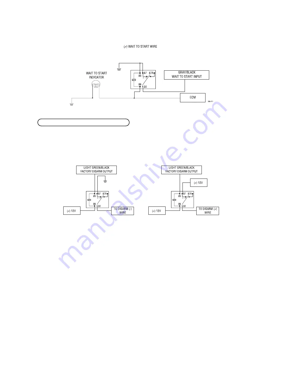
This wire sends a negative pulse every time the remote start is activated or the doors are unlocked. This can be

used to pulse the disarm wire of the vehicle's factory anti-theft device. Use a relay to send a (-) or (+) pulse to

the disarm wire as shown in the following diagrams.

Relay for Negative (-) Disarm Wire

Relay for Positive (+) Disarm Wire

H2/4 LIGHT GREEN/BLACK (-) auxiliary output

Содержание 1400XP

Страница 1: ... product is intended for installation by a professional installer only Any attempt to install this product by any person other than a trained professional may result in severe damage to a vehicle s electrical system and components Model 591XV Installation Guide ...

Страница 2: ...iring diagram 12 door lock harness H4 wiring diagram 12 remote start auxiliary harness wiring diagram 12 primary harness H1 wire connection guide 13 relay key switch interface wire connection guide 17 auxiliary harness H2 wire connection guide 18 remote start harness H3 wire connection guide 20 neutral safety switch interface 21 testing the neutral safety switch 22 1995 and newer vehicle anti thef...

Страница 3: ...n may result in property damage personal injury or death Except when performing the Safety Check outlined in this installation guide 1 Never remotely start the vehicle with the vehicle in gear and 2 Never remotely start the vehicle with the keys in the ignition The user will be responsible for having the neutral safety feature of the vehicle period ically checked wherein the vehicle must not remot...

Страница 4: ...arning lights after they lose power Disconnecting the battery requires this code to be erased which can require a trip to the dealer Remove the domelight fuse This prevents accidentally draining the battery Roll down a window to avoid being locked out of the car Test all functions The Using Your System section of the Owner s Guide is very helpful when testing Complete the vehicle Safety Check outl...

Страница 5: ... placed in a glove box or center console cannot accidentally bump it The switch fits in a 9 32 inch hole IMPORTANT When the vehicle is delivered please show the user where the Valet Program switch is located and how to disarm the system using the switch Things to remember when positioning the status LED It should be visible from both sides and the rear of the vehicle if possible It needs at least ...

Страница 6: ... in the vehicle that the security system will be connected to IMPORTANT Do not use a 12V test light to locate these wires All testing described in this manual assumes the use of a digital multimeter We recommend two possible sources for 12V constant The terminal of the battery or the constant 12V supply to the ignition switch Always install a fuse within 12 inches of this connection If the fuse wi...

Страница 7: ...xcellent place to find this wire 4 Turn the ignition key switch to the run position If your meter reads 12V go to the next step If it does not read 12V probe another wire 5 Now turn the key to the start position The meter display should stay steady not dropping by more than a few tenths of a volt If it drops close to or all the way to zero go back to Step 3 If it stays steady at 12V you have found...

Страница 8: ...ke light circuit The brake light wire is often found near the brake pedal The same wire can often be accessed in the kick panel or running board How to find a brake light wire with your multimeter 1 Set to DCV or DC voltage 12V or 20V is fine 2 Attach the probe of the meter to chassis ground 3 Probe the wire you suspect of being the brake light wire 4 Press the brake pedal If your meter shows 12V ...

Страница 9: ...s the correct wire the meter will fluctuate with the rpm of the motor and read between 1V and 6V In diesel vehicles it is necessary to interface with the wire that turns on the WAIT TO START light in the dash board This wire illuminates the bulb until the vehicle s glow plugs are properly heated When the light goes out the vehicle can be started This wire is always available at the connector leadi...

Страница 10: ...ry harness are outlined in the following wiring diagram and the wire connections are described in the wire connection guides ______ ______ ______ ______ ______ ______ ______ ______ ______ ______ ______ ______ RED WHITE 200 mA CHANNEL 2 VALIDITY OUTPUT RED CONSTANT POWER INPUT BROWN HORN H0NK OUTPUT NO FUNCTION BLACK CHASSIS GROUND INPUT NO FUNCTION BLUE SECOND UNLOCK OUTPUT NO FUNCTION BLACK WHITE...

Страница 11: ...SORY CIRCUIT RED 30A HIGH CURRENT 12V INPUT GREEN STARTER INPUT FROM IGNITION KEY SIDE PURPLE STARTER OUTPUT TO STARTER STARTER SIDE 1 2 3 4 5 6 7 8 heavy gauge relay satellite wiring diagram BLUE 200 mA STATUS OUTPUT ORANGE BLACK ANTI GRIND OUTPUT GROUND WHEN ARMED OUTPUT PURPLE 200 mA STARTER RELAY TURN ON ORANGE 200 mA ACCESSORY RELAY TURN ON PINK 200 mA IGNITION RELAY TURN ON YELLOW IGNITION I...

Страница 12: ...BLUE LOCK UNLOCK NO FUNCTION GREEN LOCK UNLOCK H4 1 H4 2 H4 3 door lock harness H4 wiring diagram BLACK WHITE NEUTRAL SAFETY SWITCH INPUT VIOLET WHITE TACHOMETER INPUT WIRE BROWN BRAKE SWITCH SHUTDOWN WIRE GRAY HOOD PINSWITCH SHUTDOWN WIRE BLUE WHITE 200 mA 2ND STATUS REAR DEFOGGER LATCHED PULSED H3 1 H3 2 H3 3 H3 4 H3 5 remote start harness H3 wiring diagram LIGHT GREEN BLACK FACTORY DISARM GRAY ...

Страница 13: ...posite position see Internal Programming Jumpers section this wire supplies a 200 mA output This is available for driving light control wires in Toyota Lexus BMW some Mitsubishi some Mazda and various other models Positive Light Flash Output Light Flash Output NOTE For parking light circuits that draw 10 amps or more the internal jumper must be switched to a light flash output See the Internal Pro...

Страница 14: ...ed it will affect both activation inputs the White Blue wire and the remote control activation Connect this wire to the optional domelight supervision relay as shown below IMPORTANT This output is only intended to drive a relay It cannot be connected directly to the domelight circuit because the output cannot support the current draw of one or more light bulbs This output is used for progressive d...

Страница 15: ...ith a factory bolt rather than your own screw Screws tend to either strip or loosen with time We recommend grounding all your components including the siren to the same point in the vehicle This wire supplies a 200 mA output that can be used to honk the vehicle horn It outputs a single pulse when locking the doors with the remote and two pulses when unlocking with the remote This wire will also ou...

Страница 16: ...When the system receives the code controlling Channel 2 for longer than 1 5 seconds the RED WHITE wire will supply an output as long as the transmission continues This is often used to operate a trunk hatch release or other relay driven function IMPORTANT Never use this wire to drive anything except a relay or low current input The transistorized output can only supply 200 mA of current Connecting...

Страница 17: ...rce of current for all the circuits the relay satellite will energize They must be connected to a high current source Since the factory supplies 12V to the key switch that is used to operate the motor it is recommended that these wires be connected there NOTE If the factory supplies two separate 12V feeds to the ignition switch connect one RED wire of the satellite to each feed at the switch Conne...

Страница 18: ...esels the wire is negative ground turns on the bulb and the GRAY BLACK can be directly connected to the wire in the vehicle If the vehicle uses a positive wire 12V to turn on the bulb a relay must be used to change the polarity See Finding the Wait To Start Bulb Wire For Diesels section of this guide Here are some common colors of this wire Chevrolet and GMC trucks Light Blue or Dark Blue Ford Tru...

Страница 19: ... activated or the doors are unlocked This can be used to pulse the disarm wire of the vehicle s factory anti theft device Use a relay to send a or pulse to the disarm wire as shown in the following diagrams Relay for Negative Disarm Wire Relay for Positive Disarm Wire H2 4 LIGHT GREEN BLACK auxiliary output ...

Страница 20: ...ng a proper signal may be more difficult See Installation Points to Remember section of this guide for finding the tachometer wire Once connected you must teach the system the tach signal See Tach Learning section of this guide Connect this wire to the toggle override switch as shown in Figure A Connect the other wire from the toggle switch to the PARK NEUTRAL switch in the vehicle This wire will ...

Страница 21: ...factured this way are most General Motors trucks sport utility vehicles and column shifting passenger vehicles Available information also indicates that pre 1996 Dodge Dakota pickups with 2 5 liter motors are also manufactured this way GM vehicles that have the neutral safety switch built into the column shifter can usually be identified by a purple starter wire Typically vehicles that use an outb...

Страница 22: ...ms in this section illustrate how to accomplish this Diagram A applies to all General Motors vehicles at the time of publication of this guide Diagram B applies to all pre 1996 Dodge Dakota pickup trucks with 2 5 liter motors This solution has one side effect if the customer inserts the key in the ignition with the driver s door open the remote start system will shut down If this inter face is use...

Страница 23: ... 2003 Directed Electronics Inc Vista CA 23 Diagram A General Motors trucks sport utility vehicles and column shifting passenger vehicles Diagram B Pre 1996 Dodge Dakota pickups with 2 5 liter motors ...

Страница 24: ... seeing the correct R code at the correct time To bypass Passlock I and II p n 555L or p n 555T is required The Passkey III system can be found in the following vehicles 97 and newer Park Avenue 98 and newer Cadillac 99 and newer U vans Transport Montana and Silhouette 2000 and newer Grand Prix Lesabre Monte Carlo Lumina Bonneville 2001 and newer Aurora Aztek and Rendezvous Other transponder based...

Страница 25: ...ce when the vehicle is started the starter and fuel pump may be disabled for up to ten minutes An optional VATS pack of resistors is available p n 652T One of the resistors in the pack will match the resistor in the key The VATS wires will be two very light gauge wires coming out of the steering column The colors of the wires vary but they are often contained in orange tubing either both will be w...

Страница 26: ...amming of the unit The unit can also be programmed using the Bitwriter When using the Bitwriter it is possible to configure any and all of the programmable functions as well as lock the Transmitter Receiver and System Features Learn Routines so that unauthorized users cannot change the configuration or program transmitters to the unit When the learn routines have previously been programmed using t...

Страница 27: ... must be switched to a light flash output P N 8617 or a standard automotive SPDT relay must be used on the H1 2 light flash output harness wire In most cases this jumper can be left in the OFF position Some new vehicles use less than 12 volts in their ignition systems The unit may have trouble learning the tach signal in these vehicles Changing the jumper to the ON setting changes the trigger thre...

Страница 28: ...ey Turn the ignition to the ON position 2 Choose Within 10 seconds press and release the Program switch the number of times cor responding to the desired channel listed below Once you have selected the channel press the switch once more and HOLD it The LED will flash and the horn will honk if connected to confirm the selected channel Do not release the Program switch CHANNEL NUMBER FUNCTION WIRE C...

Страница 29: ...you want to program Channel 2 Release the Valet Program switch Press it one time and release it to advance from Channel 1 to Channel 2 Now press and HOLD the Valet Program switch The LED will flash two times and the horn will honk twice if connected As before do not release it If you want to program Channel 3 after programming Channel 1 release the Valet Program switch press it twice and release i...

Страница 30: ...on arm disarm configurations by using the Auto learn functions in the Transmitter Receiver Learn Routine controls the Lock Panic ON Panic OFF function controls the Disarm function controls Silent Mode and an Auxiliary Output controls Remote Start controls Timer mode controls Turbo Short Run controls Channel 4 output button configuration ...

Страница 31: ... 2003 Directed Electronics Inc Vista CA 31 remote control diagram ...

Страница 32: ...ut Indicator 10 Warn Away Response Indicator 11 Siren Status Indicator 12 Battery Level Indicator 13 Trigger Response Indicator 14 Hood Switch Input Indicator 15 Ignition Switch Input Indicator 16 Sensor Response Indicator 17 Sensor 1 Indicator Full Trigger and Warn Away 18 Sensor 2 Indicator Full Trigger and Warn Away 19 Trunk Switch Input Indicator 20 Vibrate Mode Indicator 21 Remote Start Indic...

Страница 33: ...Menu Press and HOLD the Valet Program switch When the LED flashes once and the horn honks Menu One has been selected Continue to hold the switch until the LED flashes twice and the horn honks twice Menu Two has now been selected Release the switch after the Menu choice has been selected 3 Choose Within 10 seconds press and release the Valet Program switch the number of times corresponding to the f...

Страница 34: ...ss and release it once to advance from Feature 1 2 to Feature 1 3 Then press it once more and HOLD it The LED will flash in groups of 3 and the horn will honk 3 times if connected to confirm that you have accessed Feature 1 3 The learn routine will be exited if The ignition is turned on The Valet Program switch is pressed too many times More than 15 seconds elapses between programming steps One lo...

Страница 35: ...locking 1 6 Panic with ignition ON Panic with ignition OFF 1 7 Door lock pulse duration 0 8 seconds Door lock pulse duration 3 5 seconds 1 8 Double Unlock Pulse OFF Double Unlock Pulse ON 1 9 Channel 2 delayed validity Channel 2 latched 2 latch reset with ignition 3 30 second timed 4 1 10 FAD with Channel 2 ON FAD with Channel 2 OFF 1 11 Security features ON Security features OFF starter kill 1 12...

Страница 36: ...ime 0 6 sec 1 Cranking time 0 8 2 1 0 3 1 2 4 1 4 5 1 6 6 1 8 7 2 0 8 4 0 9 sec 2 6 Voltage check high level Voltage check low level 2 7 Short run turbo 1 minute 3 5 10 minutes 2 8 Activation pulse 1 1 Activation pulses 2 2 3 3 2 9 2nd Ignition output 2nd Accessory output 2 10 Accessory state during wait to start OFF Accessory state during wait to start ON 2 11 2nd status output NORMAL Rear defogg...

Страница 37: ...em can be programmed to either lock the doors when passive arming occurs or only lock the doors when the system is armed with a transmitter Active locking means the doors will not lock when the system passively arms Passive locking means that the doors will lock whenever the system passively arms the optional starter kill if connected 1 6 PANIC WITH IGNITION ON OFF This feature allows the user to ...

Страница 38: ...0 FACTORY ALARM DISARM FAD WITH CHANNEL TWO ON OFF Any time Channel 2 is activated from the remote transmitter the factory disarm output will pulse to disarm the vehicle s factory anti theft device This option can be programmed off if desired 1 11 SECURITY FEATURES ON OFF When On the security features starter kill and panic will activate if the ignition key is turned On while the doors are locked ...

Страница 39: ... the vehicle s parking lights while remote started The constant setting will turn the parking lights on solidly for the entire run duration 2 5 CRANKING TIME 0 6 0 8 1 0 1 2 1 4 1 6 1 8 2 0 4 0 If feature 2 2 is programmed to the voltage sense setting the crank time must be set to the appropriate duration The default setting is 0 6 seconds If a different crank time is desired select feature 2 5 an...

Страница 40: ...is status will activate 10 seconds after the car has started It is intended to operate the defogger circuit The output can be programmed to a latched or a pulsed output When programmed to the latched output the status will only stay active for 10 minutes 2 12 ANTI GRIND ON OFF With the anti grind On default the ground when armed output will be active during remote start operation If accessories su...

Страница 41: ...and then off 4 Release the Valet Program switch 5 Press and release the Valet Program switch The LED will now report the last system shutdown by flashing for one minute in the following grouped patterns The LED will stop flashing when the ignition is turned on LED FLASHES SHUTDOWN MODE One System timed out Two Over rev shutdown Three Low or no RPM Four Transmitter Shutdown or optional push button ...

Страница 42: ...e start can be shut off by the transmitter by pressing the remote start button and remain in timer mode but if any other shut down zones or the ignition becomes active the timer mode will cancel 1 Press Timer mode buttons 2 The vehicle will confirm with 4 parking light flashes 3 A 1 second delay will start 4 The system will start the car and will run for the specified duration unless shut down by ...

Страница 43: ...e is running press the brake pedal The engine should shut down immediately If the engine continues to run check the brake circuit connection 2 Test the HOOD PIN shutdown circuit With the vehicle in Park P open the hood Activate the remote start system The vehicle should not start If the starter engages check your hood pin and connections NOTE If programmed for Diesel Mode the system will turn on t...

Страница 44: ...d The starter cranks for six seconds but does not start Either the wrong ignition wire is being energized the unit s ignition and accessory wires have been connected backwards or the vehicle has two ignition circuits Try activating the unit with the ignition key in the run posi tion If the vehicle then runs normally retest your ignition system The starter continues to crank even though the engine ...

Страница 45: ...ediately dies 1 Does the vehicle have an immobilizer The vehicles immobilizer will cut the fuel and or spark during unau thorized starting attempts 2 Is the remote start programmed for voltage sense If so the start time may not be set high enough or you may have to adjust the voltage threshold in programming Voltage sense will not work on some vehicles 3 Check diagnostics Sometimes a shutdown will...

Страница 46: ...46 2003 Directed Electronics Inc Vista CA wiring quick reference guide ...

Страница 47: ... 2003 Directed Electronics Inc Vista CA 47 relay satellite wiring quick reference guide ...

Отзывы: