background image

D I R E C T H E A L T H C A R E S E R V I C E S . C O . U K

8

D Y N A - F O R M   M E R C U R Y   A D V A N C E

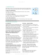
8.5 Serial Number Identification.

The serial number is made up of a combination of 3 data sets. The first four digits 

are the serial identifier. The fifth and sixth digits are the week of manufacture and the 

seventh and eighth digits represent year of manufacture.
The above pump serial number is 77785113.  

This shows that pump number 7778 was made during the week 51 year 2013.

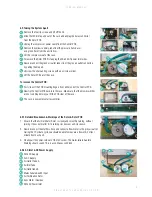
8.6 Opening the Pump Unit

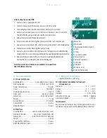
To remove the back lid from the enclosure, first unscrew the four corner screws 

(Marked A). These are No6 x 30mm Large Flange Pozi BZP self tappers.

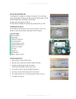
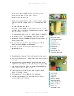
8.7 System Layout

8.8 Checking the System

1.  Plug in a mattress system to the Air Outlet.
2.  Plug in the mains cable to the IEC inlet and switch on the power.
3.   The three LED lights will flash on the control panel.  

The red LED shows that the system has low pressure.

4.  The compressor will start running and inflating the mattress.
5.  Once the system reaches 18mmHg just the LO LED will be lit.
6.  The compressor will switch on and off to regulate the mattress pressure.
7.  The system is ready for use.

 A

 A

 A

 A

DC Power Inlet 5v

Control PCB

Compressor Air Silencer

AC Power Inlet 240v

Pressure Transducer Outlet

Compressor Power Outlet

Compressor Air Outlet

Air Outlets

Rotor PCB
IEC Power Inlet
Motor / Gearbox Assembly

 1
 2
 3
 4
 5
 6
 7
 8
 9
10

11

 1

 2

 4

 3

 5

 6

 7

 8

10

11

 9

Содержание Dyna-Form Mercury Advance

Страница 1: ...D I R E C T H E A L T H C A R E S E R V I C E S C O U K Service Manual ...

Страница 2: ...reduce logistic and decontamination costs The clinical benefits of a single system are equally applicable to those of a modern hospital setting A higher maximum weight capacity up to 40 stone 254kg allows the product to meet the modern challenges of those heavier clients All component parts are interchangeable and replaceable maximising product life and reducing environmental impact Denotes when i...

Страница 3: ...ally controlled Power Unit controls a pump that allows air to flow into or out of the air cells as required according to the operating mode selected It also maintains the air pressure within the mattress at the required level and controls the action of the audible visual Audible Warning system in the event of mains supply failure or over or under inflation pressure A CPR Valve located at the pump ...

Страница 4: ...ction or indeed more pressure in the cells as they may be uncomfortable or feel as though the support surface if too soft or unstable then please select a Hi setting pressure 26mmHg This must only be used by a trained clinician as often too higher pressures can further agitate certain patients conditions When a patient requires less pressure in the cells as they may be uncomfortable or indeed hype...

Страница 5: ... be attached to the mattress as the design settings and internal air pressure properties of the Dyna Form Mercury Advance pump are specific to this mattress only The Dyna Form Mercury Advance is a replacement mattress system and should NOT be placed on top of any existing mattress The startup time from static to dynamic mode is immediate 4 2 Power Unit Pump Hang the Power Unit Pump onto the footbo...

Страница 6: ... air mattresses system whilst still utilising the advantages of the static foam inserts Repeatedly pressing the mode button enables the Lo Hi modes to be selected in turn 5 2 CPR Deflation The CPR system consists of a manually operated button located on the Air Inlet connector attached to the pump By pressing the Red Button which will release the connector locking system the user can remove the co...

Страница 7: ...it Pump 3 Clean the surface of the wash down table with Hypochlorite solution or equivalent disinfectant 4 Wash Mattress top using hot water 60 degrees C containing detergent dry with a paper towel 5 For heavy contamination use a Hypochlorite solution 1 000 parts per million available chlorine 6 Usingsuitablebrush hotwater detergentorHypochloritesolution cleanUmbilicalHoseandCPRValve Drywithpapert...

Страница 8: ... No6 x 30mm Large Flange Pozi BZP self tappers 8 7 System Layout 8 8 Checking the System 1 Plug in a mattress system to the Air Outlet 2 Plug in the mains cable to the IEC inlet and switch on the power 3 The three LED lights will flash on the control panel The red LED shows that the system has low pressure 4 The compressor will start running and inflating the mattress 5 Once the system reaches 18m...

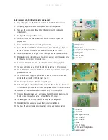
Страница 9: ... either end of the Control PCB 11 Now tip the Control PCB back into the case Make sure that the brown switches are not catching before you lift the PCB clear of the case 12 The case is now empty of all assemblies 8 9 1 Detailed Breakdown Workings of the Rotor Rotor PCB 1 Ensure that the Air Distributor Rotor is slowly and smoothly turning without jerking It does not matter if it is turning clockwi...

Страница 10: ...fed into a 5V voltage regulator 13 The 5V DC power is then fed onto the Control PCB and the Mains Failure Audible Warning Circuit Mains Failure Circuit DC Power Supply Circuit Zener Diode Dropper Capacitors 240v AC Motor Outlet Bridge Recifier 5 Amp Fuses 240v AC Power Inlet Mains Failure Switch Input 1 2 3 4 5 6 7 8 9 240v AC Outlet 5v DC Outlet 5v Regulator Smoother Capacitor Mains Failure Buzze...

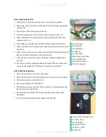
Страница 11: ...with the Air Distributor Rotor removed 12 The Air Inlet tube is connected to the Rotor Air Feeds by air channels made by the gasket under the PCB 13 The Rotor Air Feeds supply the pressurized air into the Rotor Air Seal and this distributes the air to either the Rotor Outlet A or B 14 The rotor takes 12 minutes to make a complete cycle 15 During the cycle the rotor will feed Outlet A for 5 mins th...

Страница 12: ...ould read a minimum of 80mmHg on each side 10 If one meter is reading considerably different to the other then check the gasket screws are tight enough and that the tubes do not have any perforations 8 9 5 Testing the Compressor 1 Connect the compressor to a mains power supply 2 Connect the Air outlet to a flow meter and the capil lary tube to a pressure meter 3 The Air flow should be a minimum of...

Страница 13: ... Mute LED Mute Switch Pressure Audible Warning LED Lo LED Hi LED Triac pump switch Pressure Switch Pressure Transducer 5v DC Inlet 240v Inlet Microprocessor 240v AC Pump Outlet 1 7 2 8 3 9 4 10 5 11 6 12 12 7 3 1 4 2 5 6 11 9 Technical data 9 1 Power Unit Pump Serial Number As per label on rear of pump Electrical Supply 220 240 volt 50 Hz Power Consumption 10 watts Fuses TA1H 250V Protection again...

Страница 14: ...lankets DHSstronglyadviseagainstsmokingwhilstthePowerUnit pump isinuse Thisistopreventaccidentalsecondaryignition ofitemswhichmaybeflammablee g bedlinen Thematerials usedinthemanufactureoftheMercuryAdvanceSystemcomply withtherequiredfiresafetyregulations Donotusesharpobjectsonornearthemattresssystemasthis willcausedamage Donotstoreindampconditions Donotuseinanoxygenenrichedenvironment Notsuitablef...

Страница 15: ...t on a circuit different from that to which the receiver or equipment was connected The equipment having been tested to operate within the limits of electromagnetic compatibility Immunity to interference from nearby sources radiating radio frequency energy Sources exceeding these limits may give rise to operation faults Where possible the system will sense the interference and if it is of short du...

Страница 16: ...hould be used in conjunction with appropriate clinical judgement and nursing procedures All products manufactured to standards With over 28 years experience in the provision of clinically proven value for money solutions you can be sure that our combination of innovative technologies designed in partnership with leading clinical healthcare establishments meet the needs of most patient groups inclu...

Отзывы: