D I R E C T H E A L T H C A R E S E R V I C E S . C O . U K
1 0
D Y N A - F O R M M E R C U R Y A D V A N C E
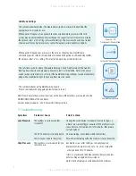
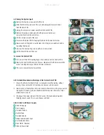
4. Unscrew the two 4BA nuts which hold the motor / gearbox into position.
Then disconnect the motor wires from the PCB connector.
5. Lift the motor off the mounting screws.
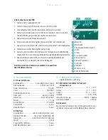
6. When 240v AC is applied to the inlet connector you should be able to get a reading
of 240v AC on both sides of the green 5 Amp fuses. If not then the fuses have
blown.
7. This would mean fitting a new Rotor PCB.
8. Before fitting a new Rotor PCB the reason why they have blown should be found,
as they are a safety net. The 500 mA / 1 Amp fuse in the IEC socket should always
blow and protect these internal fuses.
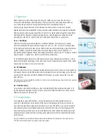
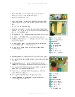
9. The DC power supply is very simple and only produces about 30-50 mA at 5v DC.
10. The 240v AC is firstly fed through the two large yellow dropper capacitors.
11. Then the output from them is fed into in the bridge rectifier which produces a raw
DC supply of about 30vDC.
12. This output is then clamped to 12v DC by the zener diode and smoothed by a
capacitor before being fed into a 5V voltage regulator.
13. The 5V DC power is then fed onto the Control PCB and the Mains Failure
Audible Warning Circuit.
Mains Failure Circuit
DC Power Supply Circuit
Zener Diode
Dropper Capacitors
240v AC Motor Outlet
Bridge Recifier
5 Amp Fuses
240v AC Power Inlet
Mains Failure Switch Input
1
2
3
4
5
6
7
8
9
240v AC Outlet
5v DC Outlet
5v Regulator
Smoother Capacitor
Mains Failure Buzzer
Battery Charging Diode
Mains Failure Relay
Mains Failure
Rechargable Battery
1
2
3
4
5
6
7
8
1
2
3
4
5
6
7
8
5
6
7
8
9
1
2
3
4
4
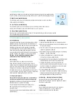
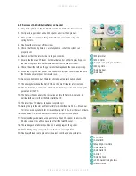
14. The photo (right) shows the position of the smoother capacitor and voltage regulator.
15. The output from the regulator is fed to the 5vDC outlet connector and also to the mains
failure circuit.
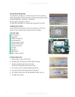
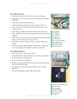
16. As soon as mains power switch is switched on, the other pole of the IEC switch
completes the circuit for the buzzer, powered by the small green rechargable battery.
17. If mains power is connected then the DC power supply generates a voltage which
switches on the relay. This breaks the buzzer circuit.
18. If the mains power is disconnected then the DC supply drops out and the relay
switches off. this activates the buzzer.
19. The rechargable battery is trickle charged through the charging diode.
20. If the battery is totally flat then it will take about 1 minute before the battery is
sufficiently charged to activate the buzzer


