DINTEK 6202-01001 Скачать руководство пользователя страница 18

Handheld Optical Power Meter


15


MAIN INDEX


Click “Finish”, Complete the installing (as per Fig. 5-13) 

5.3 Software function instruction 

This software has two functions: data processing, and the setting the instrument. 
After finishing the software installation, find the short cuts icon for this software.   


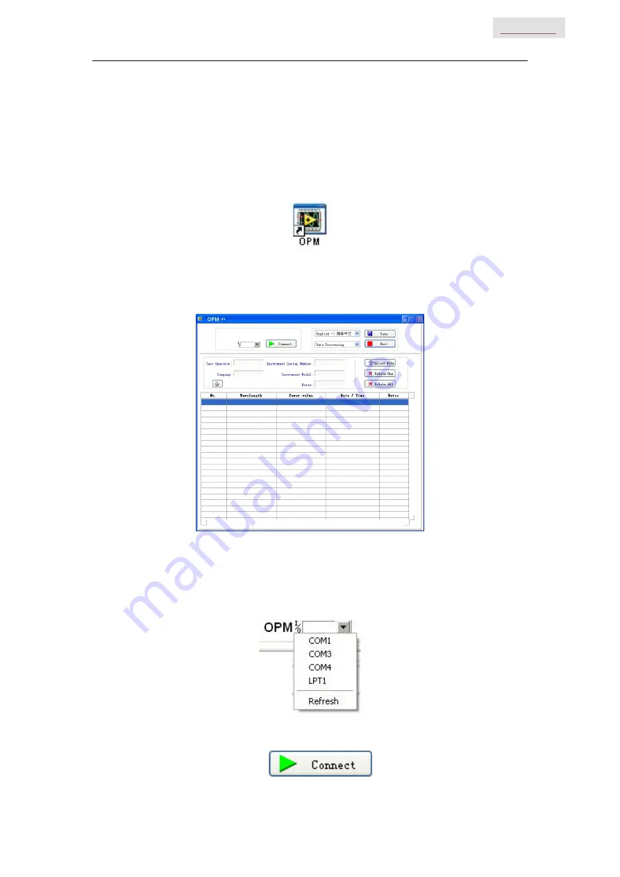
Double click this icon to open the software. You will see the software interface, (as per Fig. 5-14) 
Data processing is the default interface once the software is opened.   
5.3.1 Data Processing 


Fig. 5-14 

Data Processing interface include 4 parts. 

(1)  Manual 

I.  Port Option: Choose the right port, which the same port that the PC connects with 


II.  Connect icon, make the PC connect with the power meter, and communicate. 


Содержание 6202-01001

Страница 1: ...Handheld Optical Power Meter MAIN INDEX DINTEK Handheld Power Meter Manual...

Страница 2: ...ds should have the possibility of returning WEEE at least free of charge Safety Advice 1 When the tester use Disposable alkaline batteries do not charge it Ensure the correct polarity installation whe...

Страница 3: ...14 5 3 Software function instruction 15 Chapter 6 Operation Instruction Notes 18 6 1 Powering the Optical Power Meter 18 6 2 Power on the optical Power Meter 19 6 3 Backlight setting 20 6 4 Output Po...

Страница 4: ...like automatic wavelength identification auto wavelength switching intelligent backlight and data saving via USB port Combined with DINTEK Handheld Optical Light Source it offers a quick and accurate...

Страница 5: ...ity 1000 Communication Port USB Standard Connector FC 2 5mm universal Optional Optical Connector FC SC ST Interchangeable 2 5mm universal Optional Optical Connector LC FC SC ST Interchangeable Alkalin...

Страница 6: ...ut off after 15 minutes idle time whatever the condition of battery power supply or AC power supply Once selecting this setting the auto off will display on the left bottom of the screen This power sa...

Страница 7: ...e intelligent backlight control mode Power meter will toggle off on the backside within 15 seconds based on the outside light condition LDR is the default backlight mode Back light control key mode Pr...

Страница 8: ...the record 2 Cancel the saving When in the saving mode press to cancel the current data saving 6 Unit switch key Press the Unit key to switch between the absolute measurement dBm and relative measurem...

Страница 9: ...dB absolute value dBm and Ref value relative value absolute value Ref 8 B L SET backlight indicator Indicate backlight control mode Green light indicates LDR intelligent backlight control mode Red li...

Страница 10: ...h the AC adaptor pic 4 4 4 4 4 5 2 Mini USB Port 1 Power Supply Unit AC adaptor Notice Please use only the power supply unit supplied with the tester Use of other kinds of PSU may cause damage to the...

Страница 11: ...e When changing the optical connector take care of the connector and the end face FC connector can connect with FC adaptor 2 5mm universal connector can connect with FC SC ST adaptor Pic 4 9 4 9 Notic...

Страница 12: ...strument information 2 Bracket Collapsible metal bracket 0 90 degree can be adjusted 3 Battery Pack This unit takes 3 x 1 5v AA batteries Notice When inserting the batteries take a note of their posit...

Страница 13: ...Double click that exe program This will initiate program See fig 5 1 5 1 Click INSTALL after you will see the following Fig 5 2 5 2 Press OK to exit this install interface However the driver still has...

Страница 14: ...n problems when the power meter is connected with the P open the Device Manager right click My computer choose property pop up the property interface choose hardware option click Device Manager find t...

Страница 15: ...INDEX Fig 5 6 Fig 5 7 After successful install of the device you can switch off the power meter and disconnect the USB cable 5 2 Install the application software Run the CD in the PC find the setup fi...

Страница 16: ...Handheld Optical Power Meter 13 MAIN INDEX Fig 5 8 Press Next as per Fig 5 9 Fig 5 9 Choose I accept Click Next as per Fig 5 10 Fig 5 10...

Страница 17: ...Handheld Optical Power Meter 14 MAIN INDEX Choose I accept click Next as per Fig 5 11 Fig 5 11 Click Next as per Fig 5 12 Fig 5 12 Fig 5 13...

Страница 18: ...on find the short cuts icon for this software Double click this icon to open the software You will see the software interface as per Fig 5 14 Data processing is the default interface once the software...

Страница 19: ...own the manual to choose V Save button save the current measurement data as the EXCEL file convenience for user to view and analysis the data on the PC VI Exit button disconnect the communication clos...

Страница 20: ...ta of the instrument 5 3 2 Power Meter setting Fig 5 15 Power Meter setting interface pic 5 3 2 which include 4 parts 1 Menu bar Please refer description in data process interface 2 Calibration the us...

Страница 21: ...electricity left 40 70 electricity left 30 40 electricity left 20 30 electricity not enough electricity left less than 20 the power meter will be forced to power off Fitting the batteries as per Fig...

Страница 22: ...me on the left top of the screen there will be a as per Fig 6 3 The tester will choose AC power supply as the default when batteries are also installed Fig 6 3 When using the AC adaptor connect the po...

Страница 23: ...er long press to choose the backlight control mode 6 3 1 LDR Intelligent backlight control mode Long press B L SET is green 6 6 after 10 seconds the green LED indicates off the LDR the controller will...

Страница 24: ...cord is connected 6 4 2 Select the wavelength Short press select the calibrated wavelength notice that if the selected wavelength is not the same as the laser source wavelength it will cause an error...

Страница 25: ...g memory of 1000 records After completing the output power measurement press at the right top of the screen which will display the data saving No eg 0008 see fig 6 11 Hint Double press to confirm the...

Страница 26: ...ails of installation please refer to chapter 5 6 5 1 Opening the software Double click the icon to open the software The user can choose the language on request Chinese or English as shown in figure 6...

Страница 27: ...will pop up a successful connection window shown as 6 17 click OK to finish the connection the unit will now be communicating with the PC Fig 6 16 Fig 6 17 6 5 2 Data edit Firstly input the following...

Страница 28: ...e data display area including data delete data save and data printing Select the required data click delete one to delete it from the sheet as shown on figure 6 20 and figure 6 21 in addition The corr...

Страница 29: ...igure 6 22 click OK to delete all data also will clear all saved data from the unit 6 22 Click Save pop up a window shown in figure 6 23 input the file name choose the save path and press ok for stora...

Страница 30: ...report directly you can also print the testing report from Excel 6 5 3 Function setting on the unit Under the function setting mode you can switch the interface as shown on figure 6 25 and figure 6 26...

Страница 31: ...D operation mode press of light source to emerge light output from light source Hold down for few seconds light source will enter into Wave ID mode also AU will be shown on the upper right of LCD for...

Страница 32: ...on Power Meter Connect power meter with its same serials light source JW3116 Output frequency from MATCHED optical light source Press to emerge light from the unit press for very short second MATCHED...

Страница 33: ...ext time Chapter 7 Troubleshooting Problems Possible cause Solution Faint display on the LCD screen 1 Power is off 2 The battery power is too low 1 Press key 2 Change the batteries Inaccurate measurem...

Страница 34: ...arranty is limited to defects in workmanship and materials and does not cover damages from accident acts of god neglect wrong usage or abnormal conditions of operation 4 The company will charge corres...

Отзывы: