14
Auxiliary functions
“Energy saving”
This function manages correct functioning of the cooling fan that
only runs when strictly necessary, that is:
•
FAN MOTOR -
The fan is activated when:
- During welding or for a certain period of time after this is fin-
ished.
- When the thermostat intervenes or for a certain period of time
after it has just been reset.
Factory default
WARNING: This operation results in complete resetting of all pa-
rameters to the factory settings.
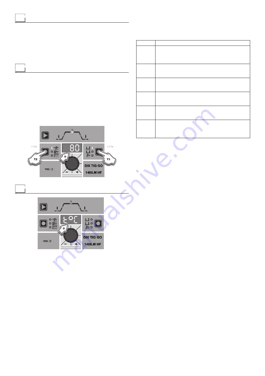
To reset the settings, you must:
•
With the machine switched on, push and hold down the WELD-
ING MODE (T1) and SELECT WELDING PROCESS (T2) but-
tons simultaneously for about 3 seconds.
•
When all the LEDs switch on at the same time, reinstatement
of the welding machine’s software to its default settings is com-
plete.
•
The message on the DISPLAY (D) reads 80.
•
The reset procedure has now been completed successfully.
Error and protection conditions
The equipment is protected against problems and if any arise the
DISPLAY shows fixed or flashing (error code) messages (depend-
ing on the type of error) that serve to inform the operator that a fault
has occurred in the equipment (see table 1).
The table provides a summary of all the error conditions that may
arise on the equipment and, if possible, what the operator must
do to attempt to resolve the problem.
Automatic reset error:
once the alarm condition has been re-
solved the equipment starts working again and the operator can
weld again!
PLEASE NOTE: If the fault persists look for the cause of the
fault and contact our technical assistance department if nec-
essary.
All of this is necessary to allow our technical assistance depart-
ment to resolve problems more easily, as quickly as possible and
thanks to the user’s reports, also because, in the meantime the
machine will not allow the operator to do their work.
Table 1
Display
Diagnosis
E0.0
POWER SUPPLY FAILURE
NON automatic reset error.
This error can only arise when switching on and not
when the welding plant is working normally.
E1.0
USER FILE MISSING
NON automatic reset error.
Immediately contact technical assistance dept.
E1.1
CONFIGURATION FILE MISSING
NON automatic reset error.
Immediately contact technical assistance dept.
E1.2
INTERNAL MEMORY ERROR
NON automatic reset error.
Immediately contact technical assistance dept.
E1.3
CALIBRATION FILE MISSING
NON automatic reset error.
Immediately contact technical assistance dept.
t°C
THERMAL PROTECTION
The welding stops due to an excessively high
temperature (thermostat activated).
Automatic reset error.
WARNING: The welding machine has a built-in electronic pro-
tective device to deal with fluctuations in mains voltage that
switches the machine off automatically (voltage exceeding
300 V), without indicating any type of error or warning mes-
sage for the operator. Subsequently it starts functioning again
automatically when the voltage has dropped to below the val-
ue indicated above.
Содержание DIX TIG GO 1406.M HF
Страница 9: ...9...


