DNDS Modular Original Betriebsanleitung Original Instruction Manual
Sicherheitstechnik Stand 19.02.2018
Date 2018-02-19
Seite 12 von 31
page 12 of 31
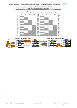
Betriebsarten und Funktion der Ausgänge
Function mode and function of the outputs
V
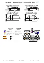
Aktuelle Geschwindigkeit
Actual speed
Vmax
Gewählte maximale Geschwindigkeit
Selected maximal speed
►
24V
Verbunden mit 24V DC
Connected to 24V DC
33 3443 44
Öffnen sofort bei V>Vmax.
Open directly at V>Vmax.
57 5867 68
*
Öffnen bei V>Vmax nur wenn nach 0,5s V>90% von Vmax
Open at V>Vmax, only if after 0,5s V>90% of Vmax.
57 5867 68
VM / VMG öffnen rückfallverzögert
t
VM / VMG open off delayed
t
Einrichtbetrieb
Tool-setting function mode
Halbautomatikbetrieb
semi-automatic function mode
Automatikbetrieb
automatic function mode
Fx
Eingangsmodule mit F-Klemmen
input modules with F-Terminals
Dx
Eingangsmodule nur mit D-Klemmen
input modules with D-Terminals only
Wichtige Hinweise
Important remarks
Bedingungen an das inkrementelle Messsystem
•
Rechteck mit 0,5-5V oder Sin/Kos, 1Vss.
•
Messsystem Frequenz
≤
300KHz
•
Hochohmigen Ausgängen im Störfall.
•
2 Spuren, 90° Phase, je Spur 2 antivalente Signale
•
Keine synthetisch erzeugten Signale.
Achtung: Wellenbruch am Messsystem ist nicht
überwacht
Requirements of the incremental measuring system
•
Signal rectangular 0.5-5V or Sin/Cos, 1Vpp
•
Measuring system frequency
≤
300KHz,
•
High resistance outputs during malfunction.
•
2 tracks 90° phase, every track 2 antivalent signals
•
Not synthetically generated signals
Attention: No monitoring of break on measuring
system axle
Grundsätzliches
•
Überwachung des absoluten Stillstands ist nicht mög-
lich.
•
Die überwachte Frequenz im Stillstand ist nach
Teiler 5Hz.
•
Bei Resolver wird auf Phasenänderung überwacht.
•
Bei inkrementellem System:
überwachte Frequenz für Einrichten 10 – 20 > über-
wachte Frequenz für Stillstand.
Fundamental
•
The monitoring of the Standstill on zero is not possi-
ble.
•
The monitored standstill frequency is 5Hz after the
divisor.
•
For resolver the change of the phase is monitored.
•
For incremental system:
monitored frequency for tool-setting 10 – 20 > moni-
tored frequency for standstill.
Nicht benützte Überwachung
Für den nicht benötigten Überwachungssteckplatz ist ein
Brückenstecker bei DINA verfügbar.
Monitoring not used
Use a bridge connector for the not needed monitoring
position. Bridge connector can be ordered by DINA.
Überwachung Stilllegen
Bei Bedarf kann eine Überwachung durch prellfreies An-
legen des Eingangs IN2 an 24V stillgelegt werden.
Disable monitoring
In case if one monitoring system should be disabled,
this could be done by connecting the input IN2 to 24V.
Fehler und Störungen
•
LED links und rechts ist dunkel.
Das Messsystem ist nicht vorhanden, Sensorfehler
•
LED links oder rechts am Eingangsmodul blinkt mit 1Hz
Spur A oder B des Messsystems fehlt.
Sensor an IN1 oder IN2 ist fehlerhaft oder fehlt.
•
LED rechts geht im Stillstand aus.
Speicherung von früheren V>Vmax. Quit: 2s Pwr aus.
•
LED links oder rechts am Eingangsmodul blinkt mit 2Hz
DNDS Störung oder Störung durch unsachgemäß ver-
legte Signalleitungen. Quit: 2s Pwr aus.
Faults and Errors
•
Dark LED left and right
No measuring system exists. Sensor failure
•
LED left or right at input module is flashing with 1Hz
Track A or B of measuring system is missing.
Sensor at IN1 or IN2 is defect or is missing.
•
LED right goes out during standstill.
Memory of previous V>Vmax. Quit: 2s Pwr off.
•
LED left or right at an input module is flashing in 2Hz
DNDS internal error or fault by improperly installed
external signal lines. Quit: 2s Pwr off.
Reaktionszeit
Die Summe der Reaktionszeit ergibt sich aus:
•
Reaktionszeit der Überwachung
•
Abfallzeit der Ausgangsrelais (<20ms)
•
Abschaltzeiten der externen Schaltelemente.
•
Reaktionszeit der Überwachung sinkt ab mit der Zu-
nahme der überwachten Drehzahl. Bei 5Hz=200ms,
1000Hz=1ms
Reaction times
The total reaction time is the sum of:
•
Reaction time of the monitoring
•
Fall time of the output relay (<20ms)
•
Switch off time of any external switching devices.
•
The reaction time of the monitoring decreases with
the increasing of the monitored speed. 5Hz=200ms,
1000Hz=1ms

