


4
Installation Instructions
This section describes how to set up your fire.
BEFORE YOU START
1. Ensure that all packing items are removed (read any warning labels carefully) and retain all packing for
possible future use e.g. in the event of moving house or returning the appliance to your supplier.
2. Before connecting the appliance, check that the supply voltage is the same as that stated on the heater.
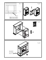
Installation into a Fireplace Mantle
●
When installing this appliance into a fireplace mantle please ensure that you choose a mantle suitable for
your appliance (Fig 17). There is to be an air vent at the front of the fireplace mantle of at least 100cm2.
It is essential to ensure that air can circulate into the appliance – otherwise the Opti-myst flame effect will
not operate correctly. This pathway for air must not be obstructed
●
Remove the 4 spacing brackets on the front of the appliance (Fig 18)
●
Slide the appliance into the fireplace mantle fully from the back ensuring that it is sitting in the center of
the mantle. Using suitable screws (not supplied) screw fix the appliance in place (Fig 19)
●
Be sure to position the fireplace within 1m of a power outlet (Fig 20)
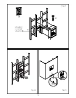
Installation into a wall or recess cavity
●
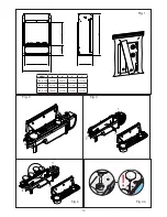
Note the product dimensions in Fig 1 and build a suitable structure for the appliance to fit into within 1m
of a power outlet (Fig21). Using suitable screws (not supplied) screw fix the appliance in place
●
Note the venting slots in the appliance. There are located at the front base and under the appliance
●
Build the wall up against the appliance using the spacing brackets as a guide.
●
There is to be an air vent at the front of the structure of at least 88cm2. It is essential to ensure that air can
circulate into the appliance – otherwise the Opti-myst flame effect will not operate correctly. This pathway
for air must not be obstructed. For examples of air vents in a wall or recess cavity see Fig 22 and Fig 23.
PLEASE ENSURE CHILDREN DO NOT CLIMB, HANG OR STAND ON THIS PRODUCT.
WARNING: THE APPLIANCE IS PROVIDED WITH A TIPPING RESTRAINT, THIS RESTRAINT IS NOT A
SUBSTITUTE FOR PROPER ADULT SUPERVISION. THIS RESTRAINT MAY PROVIDE PROTECTION
AGAINST TIPPING FURNITURE. DO NOT ALLOW CHILDREN TO CLIMB ON FURNITURE. FAILURE TO
DETACH THIS RESTRAINT BEFORE MOVING FURNITURE MAY RESULT IN INJURY AND DAMAGE.
This product is provided with a ‘Tipping Restraint Kit’ as shown in Fig 1, to prevent the product accidentally
tipping over. Fitting Instructions are supplied with this kit please follow these instructions carefully.
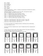
Connecting the Transducer Unit + Lamps
1. Release the two red tabs by turning them by 90 degrees (Fig 2)
2. Lift out the Sump Nozzle (Fig 3)
3. Insert lamps into lamp holders (Fig 4), carefully locating the pins into the holes (Fig 4a)
4. Push lamps firmly into place
5. Place the Transducer Unit into the sump and join the cable to the connector on the sump (Fig 5)
6. To ensure that the Transducer Unit is correctly placed in the sump, the tab on the Transducer Unit should
be lined up with the moulded recess in the sump (Fig 5a).
7. Ensure that the cable is not placed above the disc on the Transducer Unit (Fig 5b). To prevent the cable
becoming pinched between the nozzle and the sump, place the cable in the slot in the wall of the sump.
8. Replace the Sump Nozzle and secure it by turning the two red tabs by 90 degrees (Fig 6)
Содержание ENG56-400 E
Страница 14: ...14 Fig 5 Fig 5a Fig 5b Fig 6 Fig 7 Fig 8...
Страница 15: ...15 Fig 10 Fig 11 Fig 12 Fig 13 Fig 14 Fig 9...
Страница 16: ...16 Fig 15 Fig 16...
Страница 18: ...18 88cm 2 2 2 1m B C A 100cm2 100cm2 100cm2 Fig 21 Fig 22 Fig 23 X...
Страница 19: ...19...


