Dimplex DWF36-PG Скачать руководство пользователя страница 2


www.dimplex.com

Always use a qualified technician or service agency to repair this fireplace.

!

 NOTE: 

 Procedures and techniques that are considered important enough to emphasize.

 CAUTION:

  Procedures and techniques which, if not carefully followed, will result in damage to the equipment.


WARNING:

  Procedures and techniques which, if not carefully followed, will expose the user to the risk of fire, serious 

injury, or death.

OPERATION  .  .  .  .  .  .  .  .  .  .  .  .  .  .  .  .  .  .  .  .  .  .  .  .  .  .  .  .  .  .  .  .  .  .  .  .  .  .  .  .  .  .  .  .  .  .  .  .  .  .  .  .  .  .  .  .  . 3
MAINTENANCE  .  .  .  .  .  .  .  .  .  .  .  .  .  .  .  .  .  .  .  .  .  .  .  .  .  .  .  .  .  .  .  .  .  .  .  .  .  .  .  .  .  .  .  .  .  .  .  .  .  .  .  .  .  . 4
ExPLODED PARTS DIAGRAM  .  .  .  .  .  .  .  .  .  .  .  .  .  .  .  .  .  .  .  .  .  .  .  .  .  .  .  .  .  .  .  .  .  .  .  .  .  .  .  .  .  . 5
REPLACEMENT PARTS LIST  .  .  .  .  .  .  .  .  .  .  .  .  .  .  .  .  .  .  .  .  .  .  .  .  .  .  .  .  .  .  .  .  .  .  .  .  .  .  .  .  .  .  . 5
WIRING DIAGRAM  .  .  .  .  .  .  .  .  .  .  .  .  .  .  .  .  .  .  .  .  .  .  .  .  .  .  .  .  .  .  .  .  .  .  .  .  .  .  .  .  .  .  .  .  .  .  .  .  .  .  .  . 6
HEATER ASSEMbLY REPLACEMENT  .  .  .  .  .  .  .  .  .  .  .  .  .  .  .  .  .  .  .  .  .  .  .  .  .  .  .  .  .  .  .  .  .  .  .  . 7
FLICkER MOTOR REPLACEMENT   .  .  .  .  .  .  .  .  .  .  .  .  .  .  .  .  .  .  .  .  .  .  .  .  .  .  .  .  .  .  .  .  .  .  .  .  .  . 8
LED LIGHT HARNESS REPLACEMENT  .  .  .  .  .  .  .  .  .  .  .  .  .  .  .  .  .  .  .  .  .  .  .  .  .  .  .  .  .  .  .  .  .  .  . 9
ON/OFF SWITCH REPLACEMENT  .  .  .  .  .  .  .  .  .  .  .  .  .  .  .  .  .  .  .  .  .  .  .  .  .  .  .  .  .  .  .  .  .  .  .  .  .  . 10
REMOTE SWITCHbOARD REPLACEMENT   .  .  .  .  .  .  .  .  .  .  .  .  .  .  .  .  .  .  .  .  .  .  .  .  .  .  .  .  .  . 11
CIRCUIT bOARD REPLACEMENT    .  .  .  .  .  .  .  .  .  .  .  .  .  .  .  .  .  .  .  .  .  .  .  .  .  .  .  .  .  .  .  .  .  .  .  .  . 12

Remote Control Receiver 

or

 LED Driver board   .  .  .  .  .  .  .  .  .  .  .  .  .  .  .  .  .  .  .  .  .  .  .  .  .  .  .  .  .  .  .  .  .  .  .  .  .  .  .  .  .  .  .  .  .  .12

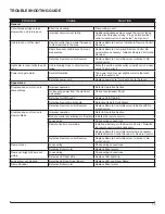
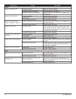
TROUbLESHOOTING GUIDE  .  .  .  .  .  .  .  .  .  .  .  .  .  .  .  .  .  .  .  .  .  .  .  .  .  .  .  .  .  .  .  .  .  .  .  .  .  .  .  .  .  . 13

TAbLE OF CONTENTS

Содержание DWF36-PG

Страница 1: ...h America Limited Dimplex North America Limited 1367 Industrial Road Cambridge ON Canada N1R 7G8 1 888 346 7539 www dimplex com REV PCN DATE 00 28 NOV 11 IMPORTANT SAFETY INFORMATION Always read this...

Страница 2: ...Procedures and techniques which if not carefully followed will expose the user to the risk of fire serious injury or death Operation 3 Maintenance 4 Exploded Parts Diagram 5 Replacement Parts List 5...

Страница 3: ...r area Operation Figure 1 The manual controls for the electric fireplace are located on the right end of the unit A On Off Switch The On Off Switch supplies power to all fireplace functions When the s...

Страница 4: ...e removed by dusting lightly with a clean dry cloth To remove fingerprints or other marks the Partially Reflec tive Glass can be cleaned with a damp cloth The Partially Reflective Glass should be comp...

Страница 5: ...0259RP Flicker Assembly 3 5902180100RP On Off Switch 4 2800070700RP Power Cord 5 4100190100RP Remote Control Receiver 6 3000820100RP Remote Switchboard 7 3000820300RP Remote Control 8 3000370900RP LED...

Страница 6: ...6 www dimplex com Wiring Diagram...

Страница 7: ...sest Wall Bracket Supports Wall Bracket Figure 3 Figure 4 Screw Locations Exterior Cover Plate Screws Back Panel Screws Front Glass Assembly Screws Bottom Panel Screws toward the front face Carefully...

Страница 8: ...nels on the left and right sides These hold the interior Partially Reflective Glass brackets in place and may cause the Partially Reflective Glass to fall and break Lift the glass assembly off the bod...

Страница 9: ...Note Be sure that the flanges on the bottom panel are positioned on the interior of the side and back panels of the fireplace The air deflector panel located on the interior of the bottom panel will...

Страница 10: ...to the lower electrical compartment In the lower electrical compartment reconnect the LED 19 light strip to the wires on the LED driver board using the 2 orange wire nut connectors Be sure to follow t...

Страница 11: ...lid ing one side of the bottom panel in place first before the second side The fit is tight and a flat instrument such as a flat head screwdriver may be helpful to guide the second side when pushing t...

Страница 12: ...left and three 3 on the right corner peak of the bottom panel two 2 in the center of the bottom panel edge toward the front face Carefully pull the bottom panel away from the fireplace 7 and rest it...

Страница 13: ...uch Appearance Fireplace does not turn on in Manual Mode Improper operation Refer to Operation Section No incoming power from the electrical wall socket Check Fuse Breaker Panel Defective On Off Switc...

Страница 14: ...r operation Defective heater assembly Replace heater assembly Heater fan turns on but heater lacks heat Improper operation Refer to Operation Section Loose wiring Trace wiring in unit Defective heater...

Отзывы: