


10
www.dimplex.com
once the fireplace is re-assembled.
Remove the two (2) screws which secure the center
10.
flicker rod support bracket in place. Set this center
support bracket aside.
Remove the twelve (12) screws which secure the bot-
11.
tom panel to the fireplace: two (2) on the left and two
(2) on the right (side flange); three (3) on the left and
three (3) on the right (corner peak of the bottom panel);
two (2) in the center of the bottom panel (edge toward
the front face).
Carefully pull the bottom panel away from the fireplace
12.
and rest it just in front of the bottom opening.
!
NOTE:
Take care not to damage the wires from the
power cord, which are still attached to the bottom panel and
the interior switches.
Inside the lower electrical housing compartment, locate
13.
the two (2) orange wire nuts. Untwist the wire-nut
connectors to separate the wires from the LED driver
board and the LED light strip. Note their original loca-
tions: yellow wire and the solid black wire connected
together; red wire and black with the orange striped
wire connected together.
!
NOTE:
The wires from the LED light strip come from
the upper compartment through the opening into the lower
compartment.
In the upper compartment, remove the 2 screws which
14.
secure the LED light strip to the light bracket. Screws
are located between the 1st and 2nd bulb and the 4th
and 5th bulb.
With wire cutters, cut the wire ties which secure the
15.
LED light strip to the light bracket, (left and right bottom
corner of the bracket).
Pull the LED light strip out of the light bracket and pull
16.
the remainder of the wires out of the protective sheath-
ing leading down into the lower compartment.
!
NOTE:
Leave the protective sheathing in place as
much as possible to reuse it with the replacement light har-
ness.
Lay the new LED light strip back into the light bracket
17.
and secure with the original 2 screws.
Feed the wires back through the protective sheathing
18.
and guide them back into their original position around
the lower corners of the light bracket, then down into
the lower electrical compartment.
In the lower electrical compartment, reconnect the LED
19.
light strip to the wires on the LED driver board using
the 2 orange wire-nut connectors. Be sure to follow the
original configuration: yellow wire and the solid black
wire connected together; red wire and black wire, with
the orange stripe, connected together
Re-connect the rubber gasket and flicker rod to the
20.
flicker motor in the upper housing.
!
NOTE:
Ensure that the flicker rod is not bent and the
bushing in the center of the flicker rod is completely set in
the support bracket. The bushing must be properly aligned
for it to go all the way down into the bracket.
Re-assemble the remainder of the fireplace in reverse
21.
order from the instructions above.
!
NOTE:
Be sure that the flanges on the bottom panel
are positioned on the interior of the side and back panels of
the fireplace.
The air deflector panel located on the interior of the bottom
panel will need to be carefully fit over the heater assembly
elements. This may take some careful maneuvering, slid-
ing one side of the bottom panel in place first before the
second side.
The fit is tight and a flat instrument such as a flat head
screwdriver may be helpful to guide the second side when
pushing the bottom panel in place. Use care to not scratch
the visible surface of the bottom.
ON/OFF SWITCH REPLACEMENT
Tools Required:
Philips head screwdriver
Flat head screwdriver
Needle-nose pliers
WARNING:
If the fireplace was operating prior to ser
-
vicing, allow at least 10 minutes for light bulbs and heating
elements to cool off to avoid accidental burning of skin.
WARNING:
Disconnect power before attempting any
maintenance to reduce the risk of electric shock or damage
to persons.
Remove the fireplace from the wall by carefully lifting it
1.
upward, releasing it from the flanges of the wall-mount
-
ing bracket. (Figure 3).
Carefully lay the fireplace down on its front.
2.
!
NOTE:
If necessary, lay a protective barrier between
the front glass and your work surface, (i.e. cloth, cardboard,
thick plastic) to avoid scratching the glass or your work
surface.
Remove the left and right side exterior cover panels
3.
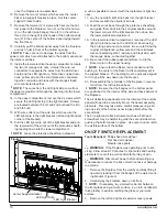
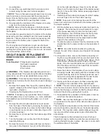
Figure 7
Center Support Bracket
LED Light Strip
LED Light Bracket
Содержание DWF36-PG
Страница 6: ...6 www dimplex com Wiring Diagram...


