background image

Signal Attenuation

If the signal strength flashes, this indicates extreme interference. Depth
and locate points may be comprised and the locator will not calibrate.

If the signal strength is not flashing but an

A

icon appears in the roll

indicator at depths shallower than 2.4 m, this is normal and you can ignore

the

A

warning.

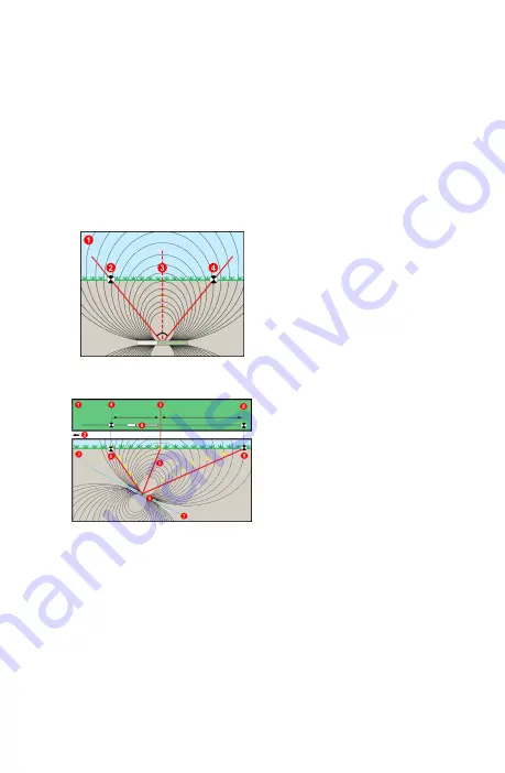
Transmitter Signal Field Geometry

Level Transmitter

1. Side view

2. RLP: Rear Locate Point
3. LL: Locate Line
4. FLP: Front Locate Point

Pitched Transmitter

1. Bird's-eye view (top down)

2. Drill rig
3. Side view (underground)
4. RLP: Rear Locate Point
5. LL: Locate Line
6. Transmitter (Tx)
7. Bore path
8. FLP: Front Locate Point

FLP and RLP are not equidistant from the LL when the transmitter is
pitched. For more information, search the

DCI DigiGuide App

for "Steep

and Deep."

- 7 -

Содержание Falcon F2+

Страница 1: ... Optimization Tx FO Toggle to menu options and click trigger to select Toggle down to find Power Off Steps Required Before Drilling 1 Scan and Pick Optimized Bands There are two methods to pick frequency bands Quick Scan Pair and Scan Pick and Pair To decide which method to use visually inspect entire site for sources of interference such as traffic loops and other utilities Pay attention to the d...

Страница 2: ...umbers 5 Quick Select Up and Down bands 6 Up band Quick Select option 7 Down band Quick Select option 8 Rescan 9 Pair 10 Exit FO Results c It is important to return to the point on the drill path with the highest noise Rescan to optimize the bands The lowest noise bands are marked with up and down arrows d You can do one of the following To continue using the currently selected bands the two on th...

Страница 3: ...pt calibration menu opens 3 Calibrate the Up Band Calibrate in an interference free environment after any pairing band change or Tx Power Mode change If you change both bands the locator and Tx calibrates the Up band first a Place the Tx in a housing on level ground and measure 3 m from the nearest edge of the locator to the center of the drill head b Click Continue to calibrate Do NOT move the lo...

Страница 4: ... Menu Use the Settings menu to set the depth units pitch units telemetry channel roll offset temperature units and LOC security settings Set the remote display to match locator settings Height Above Ground HAG Menu Height Above Ground HAG is the distance from the ground to the bottom of the locator while it is held or on a TrakStand Enabling HAG on the Main menu lets you take accurate below ground...

Страница 5: ... and RLP see Locate Mode screen on next page 4 View depth by holding the trigger at the LL on the line between the FLP and RLP 5 To improve depth data readings hold the trigger five or more seconds to enable Max Mode See the DCI DigiGuide App for more information Changing Transmitter Frequency Band Switch between Up and Down bands during pre bore calibration or mid bore to overcome interference Se...

Страница 6: ...ta will begin displaying as transmission resumes in the new band For detailed information install the DCI DigiGuide App from your smart device s App store or download the Operator s Manuals from digital control com Printed manuals are available upon request If you have questions contact your regional DCI office or Customer Service at 1 425 251 0559 or 1 800 288 3610 US CA Watch our DigiTrak traini...

Страница 7: ...al and you can ignore the A warning Transmitter Signal Field Geometry Level Transmitter 1 Side view 2 RLP Rear Locate Point 3 LL Locate Line 4 FLP Front Locate Point Pitched Transmitter 1 Bird s eye view top down 2 Drill rig 3 Side view underground 4 RLP Rear Locate Point 5 LL Locate Line 6 Transmitter Tx 7 Bore path 8 FLP Front Locate Point FLP and RLP are not equidistant from the LL when the tra...

Страница 8: ...gger held at LL 1 HAG on 2 Tx depth Depth Screen Line in the Box at LL Trigger held at FLP 1 HAG off 2 Pitch 3 Predicted depth of Tx 4 Tx battery strength 5 Horizontal distance between Tx and FLP Only valid at FLP Invalid at RLP Predicted Depth Screen Ball in the Box at FLP only The predicted depth is the depth the transmitter is calculated to be when it reaches the Front Locate Point FLP if it co...

Отзывы: