background image


Quick Start Guide for iAIS TX  V1.00 

 Web:  

www.digitalyachtamerica.com

   E-Mail

[email protected]


Installation Step 2 

– GPS Antenna 


The supplied GPS antenna is designed to be fitted to a 
standard 1”x14 TPI threaded VHF pole mount, which are 
available in many different styles from all good marine 
electronic dealers and chandleries.  


You should ensure the GPS antenna has a good clear view of 
the entire sky. It is not recommended that the GPS antenna is 
mounted up a mast where the motion of the vessel will cause 
the antenna to swing and potentially reduce the accuracy of 
the GPS position. 


Do not mount your antenna in the direct path of a radar 
transmitter. 


Feed the ten metre cable attached to the GPS antenna, 
through the pole and screw the antenna onto the pole mount 
as shown. 


Route the cable to your iAIS TX unit, adding any necessary 
extension cables. 


The GPS antenna cable is terminated in a thin FME 
connector, that is easy to route through the trunking and holes 
on a boat. It is supplied with an FME to TNC adaptor and it is 
important that once you have routed the cable through to the 
iAIS TX that this adaptor is firmly screwed in to the FME 
connector. 


Finally screw the adaptor on to the GPS connector on the iAIS 
TX. The GPS connector is the threaded TNC type connector 
to differentiate it from the AIS/VHF antenna which is 
terminated in a bayonet BNC type connector. 


Installation Step 3 - Power 


Provide power connections to the unit. Power is connected to the integral 2 core Power cable on the Red and 
Black wires. The Red wire is the positive (+) connection. The Black wire is the negative (-) connection. 


Connect the stripped wires to the nearest source of primary DC power. Ensure that the supply is connected via an 
inline 3A fuse (not supplied) or suitable circuit breaker. Add the fuse in the positive power connection to the unit if 
necessary. 


The iAIS TX Class B+ Transponder is designed for a 12V or 24v DC systems.  


Installation Step 5 

– Power Up 


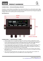
Apply power to the iAIS TX and verify that some of the LEDs flash or illuminate. 


GPS 

Antenna 

FME connector 

and adaptor apart


FME connector 

firmly screwed in 


Содержание iAIS TX

Страница 1: ...www digitalyachtamerica com iAIS TX CLASS B AIS TRANSPONDER...

Страница 2: ...and tools to complete the installation iAIS TX Class B AIS Transponder GPS antenna and cable VHF AIS antenna and cable not supplied 2 x M4 screws not supplied or other fixings appropriate to the mount...

Страница 3: ...r you can mount the antenna the better Typically at deck height reception range will be around 10NM while if you used the yacht s existing VHF antenna at the top of the mast you can expect in excess o...

Страница 4: ...runking and holes on a boat It is supplied with an FME to TNC adaptor and it is important that once you have routed the cable through to the iAIS TX that this adaptor is firmly screwed in to the FME c...

Страница 5: ...gured your product prior to supplying it to you If your AIS transceiver has not been pre configured please contact your dealer for details of how to have it configured The iAIS TX has a simple web int...

Страница 6: ...Quick Start Guide for iAIS TX V1 00 Web www digitalyachtamerica com E Mail sales digitalyacht co uk iAIS TX Web Interface...

Страница 7: ...eiving data In some apps such as the popular Navionics Boating app the iAIS TX will even be detected automatically and no app setup is required Some apps require a TCP connection for added security an...

Страница 8: ...actors that affect the transponder i e Supply Voltage GPS fix and VSWR value A series of simple Tick and Cross icons give an immediate indication of correct operation and you also have the RX and TX c...

Страница 9: ...ther you entered them in upper or lower case Select the Vessel type by clicking on the drop down list and selecting the vessel type most applicable to your vessel Finally enter the four offset measure...

Страница 10: ...start transmitting your position This continues every 30 secs whilst sailing over 2 knots or every 3 minutes whilst moored Correct operation should be verified as follows 1 Check that the green Wi Fi...

Страница 11: ...orrect operation and you will need to check the power connections for excessive voltage drop 5 Are you wirelessly connected to the iAIS TX Many mobile devices will automatically switch to another wire...

Страница 12: ...iew NMEA2000 devices on the network and if your MFD has this feature use it to check that the iAIS TX is being seen on the network and selected as the AIS source on the network NMEA2000 Interfacing A...

Отзывы: