Quick Start Guide for iAIS TX V1.00
E-Mail:
Installation Step 1
– Mechanical Mounting of the Unit
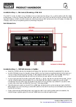
The iAIS TX can be mounted in any orientation but we recommend mounting it on a vertical surface with the cables
pointing down, so that any moisture drips down the cables and not in to the unit. The iAIS TX enclosure has two mounting
lugs which feature a 4.5mm slot. We recommend a No.8 wood screw or M4 bolt to secure the unit in place, but please do
not apply undue force when tightening which could damage the plastic.
Unit Dimensions
Installation Step 1
– VHF/AIS Antenna or Splitter
•
Install the VHF/AIS antenna (not supplied) according to the hand book instructions supplied with the antenna.
•
As with VHF Radio range, the reception range of AIS is very much antenna height dependent and the higher you
can mount the antenna the better. Typically, at deck height reception range will be around 10NM, while if you
used the yacht’s existing VHF antenna at the top of the mast, you can expect in excess of 20NM.
•
If you are going to share the boat’s existing VHF antenna i.e. use the antenna for both the VHF and AIS, you will
need to install a suitable antenna splitter. It is very important that this splitter is suitable for use with an AIS
Transponder as some of the lower cost splitters only switch one input and are only suitable for use with an AIS
receiver. We recommend our SPL2000 “Zero Loss” Technology splitter.
•
The AIS antenna connector on the iAIS TX is a BNC type connector and it may be necessary to get a PL259 to
BNC adaptor if you are connecting a normal VHF antenna to the iAIS TX as these are terminated in the standard
PL259 VHF connector.
•
Please note that Class B IS transponders only transmit at 2W so even with a perfect antenna installation, the
transmit range is typically going to be around 5-8NM based on antenna height and gain.


