


A—11
0verview
OVERVIEW
LBV00056; Revision C - 01/03/03
Lenses
Five lenses have been developed specifically for the
LIGHTNING
sx
and
LIGHT-
NING
gv
range of projectors with zoom ratios of 1.5 - 2.0:1, 2.0 - 2.5, 2.5 - 4.0:1,
4.0 - 7.0:1. In addition a fixed lens of 1.2:1 (actual 1.5:1) is available.
Using a lens adapter, the following
gv
series lenses may also be used, albeit with
modified throw ratios and limited lens shift capabilities: 0.82:1 (fixed) and zoom
lenses of 1.5 - 2.5:1, 2.5 - 4.0:1, 4.0 -7.0:1 and 7.0 - 15.0:1.
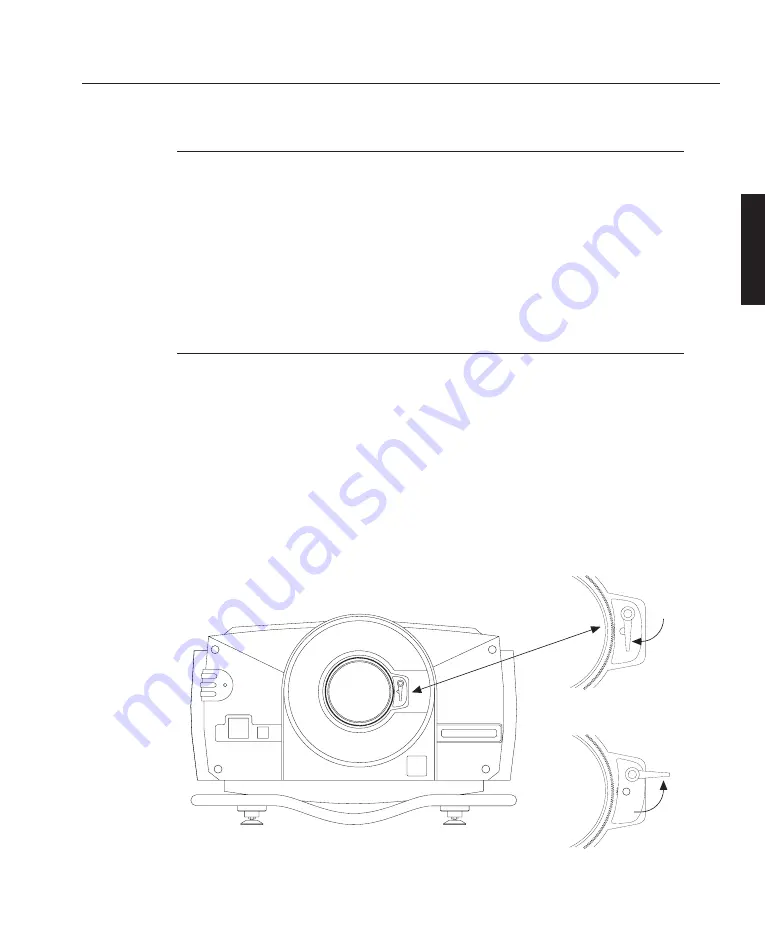
Motorised Lens Mount
The
LIGHTNING
projectors incorporate a motorised lens mount. This mounting
allows you to control the zoom/focus via the remote control.
As the lens mount attaches to the lens, the mounting mechanism must be released
before a lens can be fitted or removed. To release the lens mount turn the mounting
lever anti-clockwise (upwards). After fitting a lens the lever should be turned
clockwise to engage the mechanism.
When engaging the lens mount, the lens may have to be rotated slightly in order
for the lens mounting to connect correctly.
Lens Mount Engaged
Lens Mount Released
✍
Содержание lightning series
Страница 2: ......
Страница 4: ......
Страница 6: ......
Страница 8: ...LBV00056 Revision C 01 03 03...
Страница 14: ...Components Integrated Keypad A 16 Remote Control A 16 Overview OVERVIEW LBV00056 Revision C 01 03 03...
Страница 32: ...System Installation INSTALLATION LBV00056 Revision C 01 03 03...
Страница 138: ...Advanced User Information ADVANCED LBV00056 Revision C 01 03 03...
Страница 150: ...Appendix APPENDIX LBV00056 Revision C 01 03 03...
Страница 156: ...Appendix APPENDIX LBV00056 Revision C 01 03 03...


