


6
SCN Sensors Installation Instructions
SCN Sensors
ENGLISH
Junction Box Mount (Illustration 7c)
•
Remove extra serial number label and place in
correct install location in the sticker map or book
(Illustration 4).
•
Remove the plastic bezel.
Note:
Squeeze the two flat areas on the edge of the
bezel and pull away to release.
•
Make power and data connections (see Make Power
and Data Connections section).
•
Secure the housing to an IP65 4 inch (102 mm) round
NEMA 4 or weatherproof enclosure using the (2x)
supplied Philips screws.
•
Replace the bezel.
Verify SCN Hardware
Once the installed SCN unit, including adapter and sensor, is
powered ON, you can verify that the equipment is receiving
power by locating the SCN heartbeat. Look at the sensor
lens: Every 30 seconds, you should see a blinking red LED
indicator (Illustration 8).
Note:
Until the SCN unit is programmed using Commissioner
software, the SCN unit will use the following settings, which
effectively tell the connected luminaire(s) to remain ON at
100%, with no occupancy sensing:
•
Active Light Level: 100%
•
Inactive Light Level: 100%
•
Occupancy Sensor Delay: Sensor Inactive
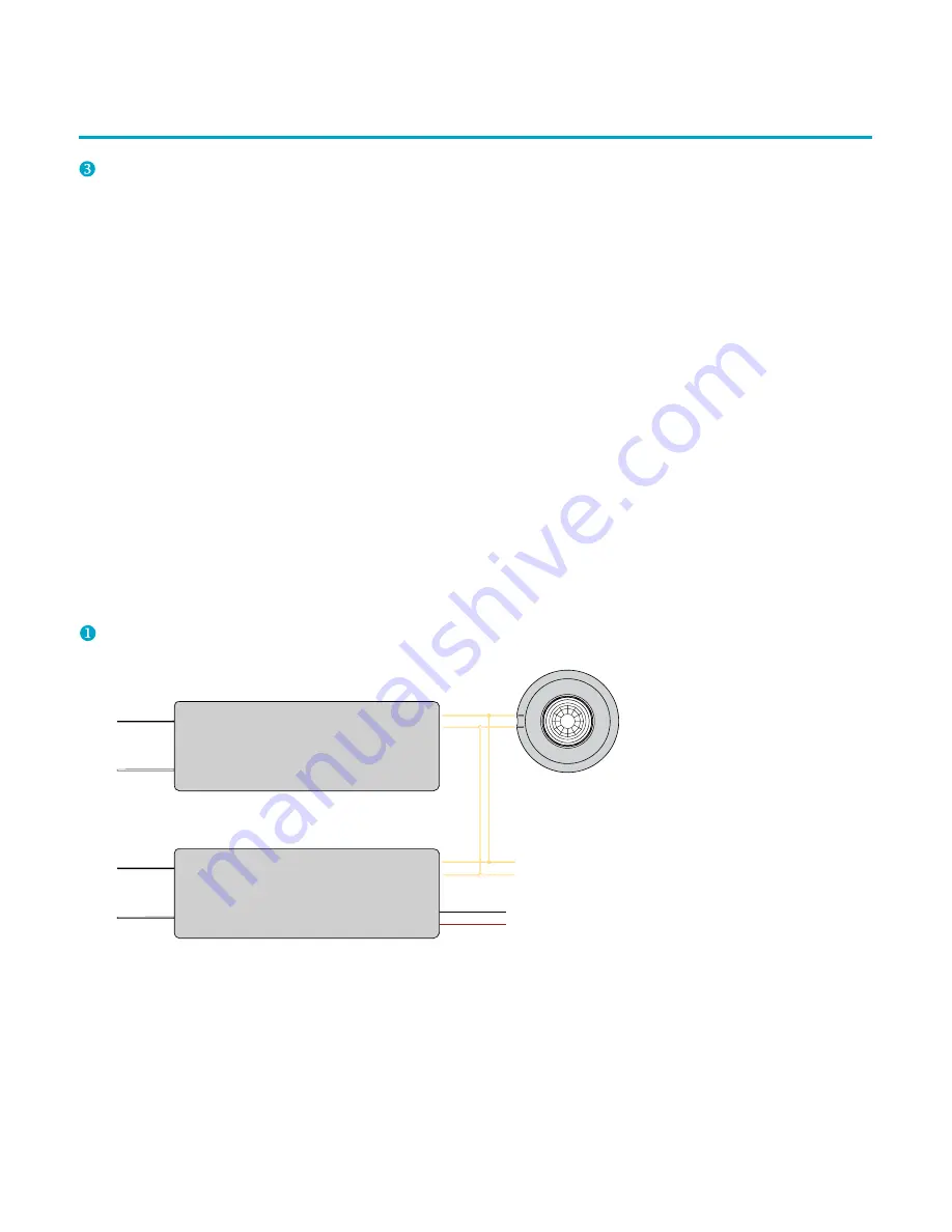
WIRING DIAGRAMS
Make Power and Data Connections
DALI
AC In
DC Out
+
–
DALI Bus Supply (Third Party)
DALI LED Driver (Third Party)
DALI –
DALI +
SCN-I, SCN-R, or SCN-S
Neutral
Line
To LEDs
Connect with up to three (3X)
additional DALI Drivers
Neutral
Line
DALI
+
–
Note:
Use 18 to 22 AWG
(0.82 to 0.33 m
2
) wiring


