background image

Prioris HX 6000 Server Powergrade Kit

8

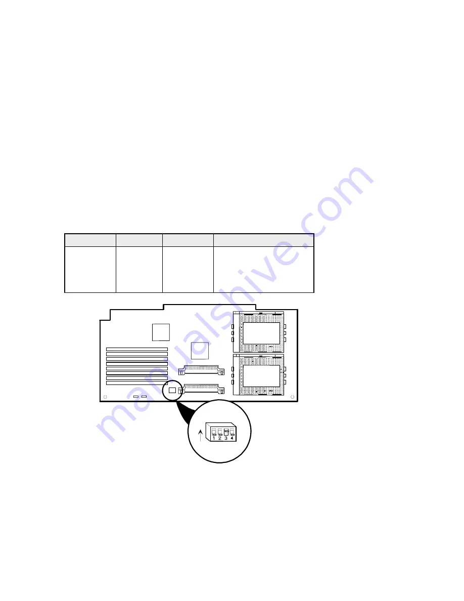
Check the Switch Settings

Check the switch settings, shown in Figure 4, for a CPU with a speed of
200 MHz as listed in Table 2 (66 MHz 

×

 3 

 200 MHz).

Table 2.  CPU Module Switch Settings

CPU Speed

Switch

Position

Description

200 MHz

SW4-1

Down

66 MHz bus frequency

SW4-2

Down

×


3 bus/core frequency

SW4-3

Up

SW4-4

Down

J8
J9
J10
J11
J12
J13
J14
J15

CPU #1

CPU #2

DEC01029-5

SW4

UP

Figure 4.  CPU Module Switch Location

Содержание Prioris HX 6000

Страница 1: ...TM Prioris HX 6000 Server Powergrade Kit Installation Guide Order Number ER PCB5U IA A01 Digital Equipment Corporation...

Страница 2: ...ncy energy and if not installed and used in accordance with the instructions may cause harmful interference to radio and television reception however there is no guarantee that interference will not o...

Страница 3: ...poration Intel and Pentium are registered trademarks of Intel Corporation MS DOS is a registered trademark of Microsoft Corporation All other trademarks and registered trademarks are the property of t...

Страница 4: ...nect the Cables 3 Power Up the Server and Update Your BIOS 5 Reset Switches on the Main Logic Board 5 Powergrade Installation 6 Remove the CPU Module 6 Install the Voltage Regulator Module s 7 Check t...

Страница 5: ...Location 8 Figure 5 Removing the SIMMs from the CPU Module 9 Figure 6 Installing the CPU Module 10 Tables Table 1 Kit Contents 1 Table 2 CPU Module Switch Settings 8 NOTE You may lose data if you have...

Страница 6: ...process has completed successfully you can then reinstall any video option card You must install the new BIOS before installing your Powergrade kit This installation guide provides the necessary deta...

Страница 7: ...5 Insert another diskette into drive A and choose Prioris HX6 Server BIOS Phlash Diskette and select Continue 6 Insert an MS DOS formatted diskette into drive A create Prioris System Configuration Uti...

Страница 8: ...ver if you attempt to remove the side panel before unplugging the ac and monitor power cords Remove any Video Option Cards Before updating the BIOS you must remove any video option card and use the em...

Страница 9: ...rade Kit 4 3 Connect the previously removed cables the monitor power cord and the server power cord to the back of the server 4 5 6 1 2 3 1 2 3 4 5 ON DEC01028 6 J57 1 2 3 J56 Figure 1 Main Logic Boar...

Страница 10: ...ted If the system loses power or if at the end of this procedure the system fails please refer to the section Troubleshooting Using the Crisis Recovery Diskette if Necessary The system will reboot at...

Страница 11: ...onnect the grounding clip to a non painted metal surface of the computer s chassis 2 Using a Phillips screwdriver unscrew and remove the CPU module retaining bracket Figure 2 3 Grasping both ends of t...

Страница 12: ...voltage regulator pins nearest the center of the new CPU module For kits AB and AC install two voltage regulator modules on the CPU module one for each CPU installed Note Any extra voltage regulator m...

Страница 13: ...ith a speed of 200 MHz as listed in Table 2 66 MHz 3 200 MHz Table 2 CPU Module Switch Settings CPU Speed Switch Position Description 200 MHz SW4 1 Down 66 MHz bus frequency SW4 2 Down 3 bus core freq...

Страница 14: ...e same order on the new CPU module 1 Press the SIMM retaining clips out A Figure 5 2 Pivot the SIMM down and pull it out of the socket B Figure 5 DEC01066 2 A A B B Figure 5 Removing the SIMMs from th...

Страница 15: ...bank must be the same type and size Check your Prioris HX 6000 System Reference Manual for the correct installation in each block Install the CPU Module 1 Install the CPU module into the dedicated CPU...

Страница 16: ...chip or module To start and run the SCU 1 Insert the SCU diskette into drive A and turn on your server The diskette should boot automatically 2 When the SCU title appears press any key to continue Af...

Страница 17: ...card and enable the onboard VGA 1 Turn off the server and set SW1 2 Figure 1 to ON Recovery mode 2 Insert the Crisis Recovery diskette into drive A and reboot the computer NOTE Remember to return swit...

Отзывы: