Digital Equipment CELEBRIS 5100 Скачать руководство пользователя страница 32

Service Procedures 

D igital C ELEBRIS Pentium  PC

32

M C S Logistics Engineering - N ijm egen

C

E

L

E

B
R

S

5
8
6

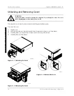
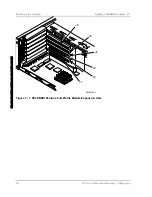
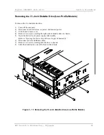
CELEBRIS Pentium Full-Profile Models

Legen
d

Description

A

Power supply

B

Main logic board

C

Front access 3½-inch diskette drive

D

Front access drive bays (supports one 5¼-inch drive and one 3½-inch drive or two 5¼-inch
drives)

E

Front internal drive bay

F

Riser card (supports up to five expansion boards; two PCI and three ISA or four ISA and one
PCI)

G

Rear internal drive bay (under power supply)

H

Front access drive bay (supports two PCMCIA slots)

DEC00320-2

A, G

B

C

D

E

F

H

Figure 3 - 5  CELEBRIS Pentium Full-Profile models

Содержание CELEBRIS 5100

Страница 1: ...Service Maintenance Manual CELEBRIS Pentium PC EK A0822 SV A01 Copyright Digital Equipment Corporation All rights reserved...

Страница 2: ...d Rights Use duplication or disclosure by the U S Government is subject to restrictions as set forth in subparagraph c 1 ii of the Rights in Technical Data and Computer Software clause at DFARS 252 22...

Страница 3: ...Setting High Resolution Mode for The Monitor Display 15 SMODE EXE 15 SMTR EXE 16 DOS Video Drivers 17 Windows 3 x Drivers 17 BIOS SETUP UTILITY 17 Running the BIOS Setup Utility 18 Helpful Hints 18 B...

Страница 4: ...Tabl e ofC ont ent s Di gi t alC ELEBRI S Pent i um PC 4 M C S Logi st i csEngi neer i ng Ni j m egen C E L E B R S 5 8 6 BIOS Version Information 29 UNLOCKING AND REMOVING COVER 30...

Страница 5: ...5 Removing the 3 Inch Diskette Drive Full Profile Models 46 Removing the Main Logic Board 48 Removing the Power Supply Low Profile Models 49 Removing the Riser Card Bracket 51 INSTALLATIONPROCEDURES 5...

Страница 6: ...SIMM Socket Locations 41 Figure 3 10 Release Front Locking Mechanism 42 Figure 3 11 Lock in place 43 Figure 3 12 Opening the Full Profile Device bay Power Supply Assembly 44 Figure 3 13 Removing the 3...

Страница 7: ...e computer s to be serviced since many of the diagnostic tests are designed to test more than one product CAUTION Digital recommends that only A certified engineers attempt to repair this equipment Al...

Страница 8: ......

Страница 9: ...ile enclosure with 75 MHz Pentium CELEBRIS 590 low profile enclosure with 90 MHz Pentium CELEBRIS 590 FP full profile enclosure with 90 MHz Pentium CELEBRIS 5100 low profile enclosure with 100 MHz Pen...

Страница 10: ...E WC 1 44MB 540MB 8MB 256KB CELEBRIS 590 FR 832WW AC 1 44MB 8MB 256KB FR 832E WB 1 44MB 270MB 8MB 256KB FR 832E WC 1 44MB 540MB 8MB 256KB FR 832E WD 1 44MB 840MB 16MB 256KB CELEBRIS 575 FR 833WW AC 1...

Страница 11: ...EXE enables to upgrade or restore the computer s BIOS via Flash ROM EPP3SMC EXE enables to configure the computer for EPP operation Logitech mouse drivers enables the computer to operate using a Logit...

Страница 12: ...copy of the system utilities Creating a Crisis Recovery Diskette A crisis recovery diskette should always be prepared before attempting to upgrade the BIOS This diskette is used to reprogram the BIOS...

Страница 13: ...ms and or video drivers it is recommended to follow the procedures in the order given 1 Turn on or reboot the computer If POST detects an error refer to Troubleshooting for possible causes and suggest...

Страница 14: ...es C onf i gur at i on Di gi t alC ELEBRI S Pent i um PC 14 M C S Logi st i csEngi neer i ng Ni j m egen C E L E B R S 5 8 6 A screen appears on the monitor warning that you are about to erase the com...

Страница 15: ...DOS Video Drivers Windows 3 x Drivers Setting High Resolution Mode for The Monitor Display To use the high resolution modes on the computer perform the following steps 1 Use the BIOS Setup utility to...

Страница 16: ...monochrome adapter SMTR EXE The video controller s monitor type selection must match the monitor s available resolution and refresh rates These monitor resolution and refresh rates are listed in the...

Страница 17: ...he SETUP screen 3 Select the MWTPE option and press Enter 4 Toggle through the MWTPE option to select the appropriate Windows 3 x driver 5 Select the desired video resolution then press Enter 6 If the...

Страница 18: ...tion errors listed and then press F2 to display the main menu 3 Follow the instructions on screen and any on line help pop up screens to configure the computer Helpful Hints Several keyboard function...

Страница 19: ...epending on the language kit that has been ordered Diskette A Diskette B 1 44 MB 3 2 88 MB 3 Not Installed 360 KB 5 1 2 MB 5 720 KB 3 Sets the size and density of diskette drives Video system EGA VGA...

Страница 20: ...Pent i um PC 20 M C S Logi st i csEngi neer i ng Ni j m egen C E L E B R S 5 8 6 Floppy check Enabled Disabled Enabling this option causes the computer to verify the diskette type each time the comput...

Страница 21: ...Displays the number of cylinders Heads 1 to 64 Displays the number of heads Sectors track 0 to 63 Displays the number of sectors tracks Landing zone 0 to 4095 Displays the number of cylinders specifie...

Страница 22: ...ns to repeat a keystroke Memory and Cache Options Menu Fields Settings Comments Internal cache Enabled Disabled Enables or disables the computer s internal cache External cache Disabled Enabled Enable...

Страница 23: ...allel port Auto Disabled 3BC IRQ 7 378 IRQ 7 278 IRQ 5 Enables or disables the onboard port at the specified address Parallel port mode Compatible mode Bi directional mode Sets the onboard parallel po...

Страница 24: ...t i es C onf i gur at i on Di gi t alC ELEBRI S Pent i um PC 24 M C S Logi st i csEngi neer i ng Ni j m egen C E L E B R S 5 8 6 IDE adapter 0 1 Enabled Disabled Enables or disables the onboard IDE co...

Страница 25: ...m power saving state Monitor off timer Disabled 1 min 5 min 10 min 20 min 30 min Allows to disable the monitor off feature or after a set period of keyboard or mouse inactivity to place the monitor in...

Страница 26: ...password Press Enter Enables to set a supervisor password Set user password Press Enter Enables to set a user password Password on boot Enabled Disabled Enables or disables the enter password on boot...

Страница 27: ...ected Keep circuit boards and components away from non conductors Keep clothing away from circuit boards and components Keep circuit boards in anti static bags Be cautious when AC power is exposed whe...

Страница 28: ...r that is used in house Special Tools Required None Remedial Diagnostic Test Software QAPLUS fe PC Advanced Diagnostic Software latest version Supplier information Diagsoft Inc 5615 Scotts Valley Driv...

Страница 29: ...Ltd Paivantaite 8 FIN 02210 ESPOO FINLAND tel 358 0 478 444 fax 358 0 478 44 599 e mail f prot datafellows fi Internet http www datafellows fi Data Fellows Ltd homepage ECO FCO Information BIOS Versi...

Страница 30: ...monitor power cords The computer s cover must be removed prior to installing any hardware option To remove the cover 1 Unlock cover 2 Lift both side locks out then turn towards front of computer to r...

Страница 31: ...m Low Profile Models Legen d Description A Power supply B Main logic board C 3 inch diskette drive D Front access drive bay E Front internal drive bay F Riser card two PCI and one ISA or two ISA one P...

Страница 32: ...ont access 3 inch diskette drive D Front access drive bays supports one 5 inch drive and one 3 inch drive or two 5 inch drives E Front internal drive bay F Riser card supports up to five expansion boa...

Страница 33: ...n Plug and Play expansion boards run the ISA Configuration Utility ICU to configure the computer to avoid resource conflicts Expansion Slot Slot Type Description J4 ISA Supports full length industry s...

Страница 34: ...ce Pr ocedur es Di gi t alC ELEBRI S Pent i um PC 34 M C S Logi st i csEngi neer i ng Ni j m egen C E L E B R S 5 8 6 Figure 3 6 CELEBRIS Pentium Low Profile Models Expansion slots DEC00300 2 J 4 J3...

Страница 35: ...boards Uses the top three expansion slot at the rear panel J3 ISA Supports full length industry standard 16 bit ISA expansion boards Uses the fourth expansion slot at the rear panel Designated as a s...

Страница 36: ...Pr ocedur es Di gi t alC ELEBRI S Pent i um PC 36 M C S Logi st i csEngi neer i ng Ni j m egen C E L E B R S 5 8 6 Figure 3 7 CELEBRIS Pentium Full Profile Models Expansion slots DEC00348 2 J6 J5 J4...

Страница 37: ...d setting Press the jumper evenly onto the pins Be careful not to bend the pins CAUTION Do not touch any electronic component unless you are safely grounded Wear a grounded wrist strap or touch an exp...

Страница 38: ...ELEBRI S Pent i um PC 38 M C S Logi st i csEngi neer i ng Ni j m egen C E L E B R S 5 8 6 CELEBRIS Pentium Main Logic Board Jumper Locations Figure 3 8 CELEBRIS Pentium Main Logic Board Jumper Locatio...

Страница 39: ...MB Fill bank 0 before bank 1 See figure 3 9 Socket 0 Socket 1 Socket 2 Socket 3 Total 4 MB 4 MB 8 MB 8 MB 4 MB 4 MB 8 MB 4 MB 4 MB 4 MB 12 MB 4 MB 4 MB 8 MB 16 MB 4 MB 4 MB 4 MB 4 MB 16 MB 8 MB 8 MB...

Страница 40: ...0 Socket 1 Socket 2 Socket 3 Total 4 MB 4 MB 32 MB 32 MB 72 MB 32 MB 32 MB 4 MB 4 MB 72 MB 32 MB 32 MB 8 MB 72 MB 8 MB 8 MB 32 MB 32 MB 80 MB 32 MB 32 MB 8 MB 8 MB 80 MB 32 MB 32 MB 16 MB 80 MB 16 MB...

Страница 41: ...Digital CELEBRIS Pentium PC Service Procedures MCS Logistics Engineering Nijmegen 41 Figure 3 9 CELEBRIS Pentium SIMM Socket Locations...

Страница 42: ...y Open the device bay power supply subassembly in order to install remove and or connect certain components and peripheral devices To open the subassembly 1 Turn off the computer 2 Disconnect external...

Страница 43: ...Digital CELEBRIS Pentium PC Service Procedures MCS Logistics Engineering Nijmegen 43 Figure 3 11 Lock in place DEC0029 2 2...

Страница 44: ...ly subassembly in order to install remove and or connect certain components and peripheral devices To open the subassembly 1 Turn off the computer 2 Disconnect external devices ac power and monitor po...

Страница 45: ...and monitor power 3 Unlock and remove cover 4 Remove two screws securing the right side of diskette drive to chassis 5 Open the device bay power supply subassembly Refer to Opening the Device Bay Powe...

Страница 46: ...computer 2 Disconnect external devices ac power and monitor power 3 Unlock and remove cover 4 Remove two screws securing the right side of diskette drive to chassis 5 Open the device bay power supply...

Страница 47: ...Digital CELEBRIS Pentium PC Service Procedures MCS Logistics Engineering Nijmegen 47 Figure 3 14 Removing the 3 Inch Diskette Drive Full Profile Models...

Страница 48: ...g the Main Logic Board To remove the Main Logic Board 1 Turn off the computer 2 Disconnect external devices ac power and monitor power 3 Unlock and remove cover 4 Remove all connectors 5 Remove all ex...

Страница 49: ...gic board noting their proper orientation 3 While holding the device bay and power supply subassembly carefully release the rear latch 4 Carefully slide entire subassembly away from chassis and place...

Страница 50: ...Ser vi ce Pr ocedur es Di gi t alC ELEBRI S Pent i um PC 50 M C S Logi st i csEngi neer i ng Ni j m egen C E L E B R S 5 8 6 Figure 3 18 Removing the Full Profile Models Power Supply...

Страница 51: ...Card Bracket To remove the riser card and bracket 1 Turn off the computer 2 Disconnect external devices ac power and monitor power 3 Unlock and remove cover 4 Remove all expansion boards 5 Carefully l...

Страница 52: ...Ser vi ce Pr ocedur es Di gi t alC ELEBRI S Pent i um PC 52 M C S Logi st i csEngi neer i ng Ni j m egen C E L E B R S 5 8 6 Figure 3 20 Removing the Riser Card Bracket Full Profile Models...

Страница 53: ...he holes in the card with the plastic inserts and then snap into place Also do not remove the external cache module Removing the external cache module prevents the computer from operating correctly To...

Страница 54: ...Ser vi ce Pr ocedur es Di gi t alC ELEBRI S Pent i um PC 54 M C S Logi st i csEngi neer i ng Ni j m egen C E L E B R S 5 8 6 Figure 3 21 Installing a Higher Performance CPU DEC00299 2 A...

Страница 55: ...e of the installed CPU Future CPU upgrades might also require an external cache module upgrade NOTE If you install a higher performance CPU a 3 3V dc external cache module might be required and comes...

Страница 56: ...Ser vi ce Pr ocedur es Di gi t alC ELEBRI S Pent i um PC 56 M C S Logi st i csEngi neer i ng Ni j m egen C E L E B R S 5 8 6 Figure 3 22 Installing External Cache Memory...

Страница 57: ...DRAM chip in the designated socket on the main logic board To install the video memory upgrade chip 1 Turn off the computer 2 Disconnect external devices ac power and monitor power 3 Unlock and remove...

Страница 58: ...he computer s battery might be considered hazardous waste Make sure you follow any state or local statute to properly dispose of the old battery To replace the battery perform the following 1 Record c...

Страница 59: ...Digital CELEBRIS Pentium PC Service Procedures MCS Logistics Engineering Nijmegen 59 Figure 3 24 Replacing the computer s Battery DEC0029 9 4...

Страница 60: ...ice s socket should be marked with an arrow at one end of socket If necessary refer to the device s documentation for pin 1 orientation 2 Connect appropriate power cable to device 3 Replace and lock s...

Страница 61: ...Digital CELEBRIS Pentium PC Service Procedures MCS Logistics Engineering Nijmegen 61 Figure 3 25 Diskette Drive Connection DEC0030 3 2 A B C E E D...

Страница 62: ...n C E L E B R S 5 8 6 Connecting IDE Devices Figure Legend IDE Drive Component Figure 3 26 A Power supply B Power connections C IDE hard disk drive connections D Main logic board IDE drive connections...

Страница 63: ...sk drives are spun down completely and then turn it back on If the POST detects an error refer to Troubleshooting and take the appropriate steps to correct the problem After the problem has been resol...

Страница 64: ...are software and firmware or to provide operating information about the computer Each time the POST displays a message on screen the computer s speaker beeps twice If an error occurs before the monito...

Страница 65: ...tor type does not match CMOS Run SETUP Run the BIOS Setup utility and set the correct monitor type Operating system not found The operating system cannot be found on drive A or drive C Run the BIOS Se...

Страница 66: ...m PC 66 M C S Logi st i csEngi neer i ng Ni j m egen C E L E B R S 5 8 6 System cache error Cache disabled RAM cache failed Run the BIOS Setup utility and restore all settings to original values If th...

Страница 67: ...d segments of the BIOS that can be reclaimed by a virtual memory manager Video BIOS shadowed This indicates that the computer s video BIOS was successfully copied to shadow RAM Computer Troubleshootin...

Страница 68: ...on board Expansion board installed incorrectly Did not run ICU to configure expansion board before installation Expansion board has failed Remove expansion board and reinstall Run the ICU to properly...

Страница 69: ...he module installed incorrectly External cache module has failed Remove external cache module and reinstall Replace external cache module Computer fails to retain setup information Computer battery ha...

Страница 70: ...ce SCSI device jumpers incorrectly set SCSI cable not terminated SCSI device not plugged in Terminating resistors not removed from the SCSI device SCSI adapter failure SCSI ID conflicts Refer to the s...

Страница 71: ...iskette drive not enabled Diskette boot option disabled Onboard diskette controller disabled Diskette does not contain start up files Make sure the drive ID is correctly set Run the BIOS Setup utility...

Страница 72: ...DE connector There might be a boot sector virus Hard disk boot sector is missing Install the appropriate operating system Format the IDE hard disk drive or partition the IDE hard disk drive using the...

Страница 73: ...sible Cause Action IDE SCSI hard disk drive cannot read or write information Incorrect disk drive jumper settings Loose or incorrectly installed cables IDE drive type incorrect Onboard IDE interface d...

Страница 74: ...onitor type Refer to appropriate video driver documentation Distorted rolling or flickering screen display or wrong uneven color Monitor incorrectly adjusted Monitor signal cable incorrectly installed...

Страница 75: ...Run Setup Check connections Reset controller Replace controller Replace disk Floppy diskette Media Mismatch Drive Not Ready Write Protected Media Unformatted Media Use known good diskette Check size a...

Страница 76: ......

Страница 77: ...onflict results and the expansion board will not operate as expected Note that some memory I O and interrupt locations can be changed using the BIOS Setup utility CAUTION Before changing any memory or...

Страница 78: ...MA controller two 0F0 Clear math coprocessor busy 0F1 Reset math coprocessor 0F8 0FF Math coprocessor 170 177 Secondary IDE controller 1F0 1F7 Primary IDE controller 278 27A LPT2 2E8 2EF COM4 2F8 2FF...

Страница 79: ...7 LPT1 LPT3 if enabled IRQ8 RTC IRQ9 IRQ11 Reserved IRQ12 Mouse interrupt if enabled IRQ13 Math co processor IRQ14 IDE primary if enabled IRQ15 IDE secondary if enabled DMA Channel Assignment Channel...

Страница 80: ......

Страница 81: ...tructive test and Sequential write random read destructive test Floppy Disk all tests Keyboard all tests COM Ports all tests LPT Ports all tests Pointer Device all tests 3 Successful bootstrap of the...

Страница 82: ......

Страница 83: ...Digital CELEBRIS Pentium PC Service Notes MCS Logistics Engineering Nijmegen 83 Appendix A Service Notes This appendix contains the current Service Notes for the CELEBRIS Pentium product line...

Страница 84: ......

Страница 85: ...IA English ER 830WW IG German ER 830WW II Italian ER 830WW IS Spanish ER 830WW IP French CELEBRIS Pentium low Profile Users Guide ER 830WW UA English ER 830WW UG German ER 830WW UI Italian ER 830WW U...

Страница 86: ...technical tips can be found on all of these bulletin boards DECpc Bulletin Board Server DECpc BBS provides an easy to use menu driven bulletin board providing on line access to the latest PC product i...

Страница 87: ...best to make this document a valuable support to your service efforts for Digital Please fill out the reader feedback form and send or fax it to Digital Equipment Parts Center b v Att MCS Logistics En...

Страница 88: ......

Страница 89: ...Personal Notes...

Страница 90: ...Personal Notes...

Страница 91: ...Personal Notes...

Страница 92: ...Personal Notes...

Страница 93: ...ommitments submitted on this form are used at Digital s direction Did you find errors in this manual If so specify by page What is your general reaction to this manual format completeness organisation...

Страница 94: ...Name Title Company Dept Address City State Country...

Отзывы: