Installing System Options
AlphaStation 500 Series User Information 3-17
1.
Orient the bracket, as shown in Figure 3-9. Position the drives so that the cable
connections face to the rear of the system. Select the bracket mounting holes that
match the threaded holes in the drives. Mount the drives in the tray bracket, securing
them with the four screws provided with each drive.
2.
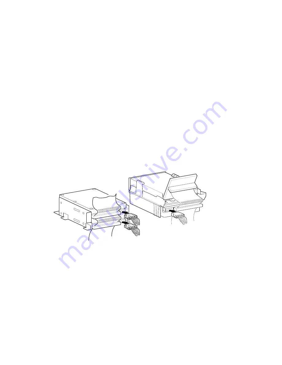
Connect the power and SCSI cables to the drives before fully inserting and securing
the devices. Refer to Figure 3-10, which depicts the rear view of both storage bays.
Figure 3-10 shows, in this example, the SCSI bus and power cabling configuration for
two optional 3.5-inch x 1.0 inch SCSI hard drives, in the bay beneath the CD-ROM.
Also shown, is the floppy drive bracket with the SCSI and power cabling for the one
optional 3.5 inch x 1 inch SCSI hard drive (in the lower position, beneath the floppy
drive).
MA00968
Figure 3-10 Cabling the Optional Hard Drives
3. Replace the drive tray into the lower right side storage bay. Slide the bracket forward
until it locks in place. Refer to Figures 3-11 through 3-15 for cable additional cable
configurations.
Verify that the cables are connected in the correct orientation. All cables and most
connectors are keyed so that you cannot connect them incorrectly. If your drive is not
keyed, you must connect pin 1 of the cable to pin 1 of the connector.
Pin 1 of the cable is on the edge with the colored stripe or pattern. Pin 1 of the
connector should be marked with a small number "1" at one end of the connector or
with a small number “1” or “2” printed on the circuit board near one end of the
connector.
4.
Replace the CD-ROM bracket assembly. Slide it forward until it locks in place.
5.
Connect the power cord and plug it into the wall outlet.


