


DVM-500Ultra Installation Guide REV B
Page 14
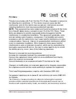
STEP 9:
Wireless Microphone Charging Cradle
Mount the wireless MIC charging cradle in a desirable location, plug the power
cable into the charging cradle, then connect the cigar plug to a constantly
p12V receptacle. Mounting hardware is included, and there are 2
threaded mounting holes in the bottom of the charging cradle allowing you
several mounting options.
A 110 Volt AC Wall charger is also provided for charging outside the vehicle.
YOUR DVM INSTALLATION IS COMPLETE. TURN ON THE VEHICLE’S IGNITION, INSERT THE CF CARD INTO
THE DVM-500ULTRA, AND PRESS THE “MARK” BUTTON ON THE DVM TO POWER ON THE SYSTEM. IF
INSTALLING THE OPTIONAL WIRELESS TRANSFER MODULE, CONSULT THE WTM-555 INSTALLATION GUIDE.
IMPORTANT NOTES WHEN INSTALLING AND USING YOUR DVM-500ULTRA
The DVM’s CF memory card comes with 2 default login settings already configured, and they are as
follows:
User1
– Password = 222222
Admin
– Password = 111111
A CF Memory Card Must Be Installed. Your DVM has been shipped with a 4GB CF memory card. A
memory card must be fully inserted before powering up the unit or a message “Error – CF Missing or
Bad” will appear on the screen and the unit will fail to start up. Although your CF card is ready to use
out of the box, it should be activated through your back office software. Consult the
DVM-500Ultra
User’s Guide
, and the
VideoManagerII™
or
VuVault™ User’s guides
for information on activating your
CF card.
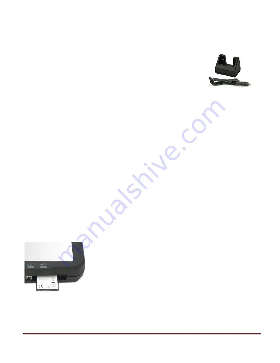
DO NOT FORCE MEMORY CARDS INTO THE SLOT
The card only goes in one way, with the back side of the card towards the front of the mirror and the
colorful label side facing the back of the mirror. The memory card should slide in very easily and you
should only encounter resistance as the last 1/8” snaps into place. If the card is difficult to insert, pull it
back out and make sure it is facing the right direction and align it carefully with the slot as you reinsert
it.
Important: Do Not Insert or Remove the Compact Flash Card while the
unit is Powered On.
Important: Before Jump Starting the Vehicle
,
all power should be
removed from the system. Remove the (2) 7.5 Amp fuses from the side of
the I/O Box BEFORE jump-starting the vehicle. This will prevent
potentially damaging voltage spikes from entering the DVM-500Ultra
System. Reinsert the fuses after jump-starting the vehicle.


