


DVM-500Ultra Installation Guide REV B
Page 13
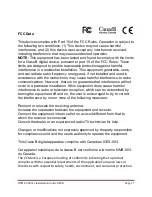
Wiring Connections Chart
Input Signal
Color
AWG
Description
Notes
+12V Power
16
+12VDC Un-switched Power
REQUIRED
. Digital Ally recommends
connecting directly to the engine
compartment battery. Do NOT
connect to a charge guard or battery
saver system.
Ground
16
Ground
REQUIRED
. Digital Ally recommends
connecting directly to the engine
compartment battery
Ignition
18
+12VDC Switched
REQUIRED
. +12V power only when
ignition is in the ACC or On position.
When ignition is turned off, the unit
Can be set to do a controlled
shutdown automatically based on a
user selectable time setting. This
connection also necessary to charge
the I/O box internal backup battery.
Emergency Lights
18
Emergency Light interface. +12V when
lights are activated
Connect to Light Bar Controller
Siren
18
Connect directly to one side of siren
speaker. Or, connect one yellow wire to
siren controller if it o12VDC when
siren is ON.
Siren
18
Connect directly to other side of siren
speaker. Or, connect other yellow wire to
ground if the siren controller outputs
+12VDC when siren is ON.
Brake
18
Brake interface. +12V signal when brakes
are activated
Connect to brake pedal switch or 3rd
brake light
Speed
18
Vehicle speed sensor for speedometer
interface. (VSS)
Speed sensor that outputs X number
of pulses per mile.
Left Turn Signal
18
Left turn signal input. +12V signal when turn
signal is activated
Right Turn Signal
18
Right turn signal input. +12V signal when
turn signal is activated
Reverse
18
Reverse input. Signal grounded when
vehicle goes into reverse
N
N
O
O
T
T
E
E
The interface box includes a battery backup that provides between 30-90 minutes of operation in the case of
unexpected power loss, and is kept charged while the vehicle is running. If the Backup Battery does not have a high
enough charge at the time of installation, the DVM may not power up correctly the first time. It may be necessary to
charge the backup battery in the IF Box prior to first use. To charge the Backup Battery, start the vehicle and allow it
to run for at least 5 to 10 minutes following installation.
N
N
O
O
T
T
E
E
The ignition input (Blue wire) MUST be connected to a point where +12V is present only when the ignition is in the
ON position.


