Digi HI-700HS Скачать руководство пользователя страница 212

HI

-

700HS service manual 

-

 4 –


servicing


  4

-

103                                                   Issue 2   06/2020


Labeller 

-

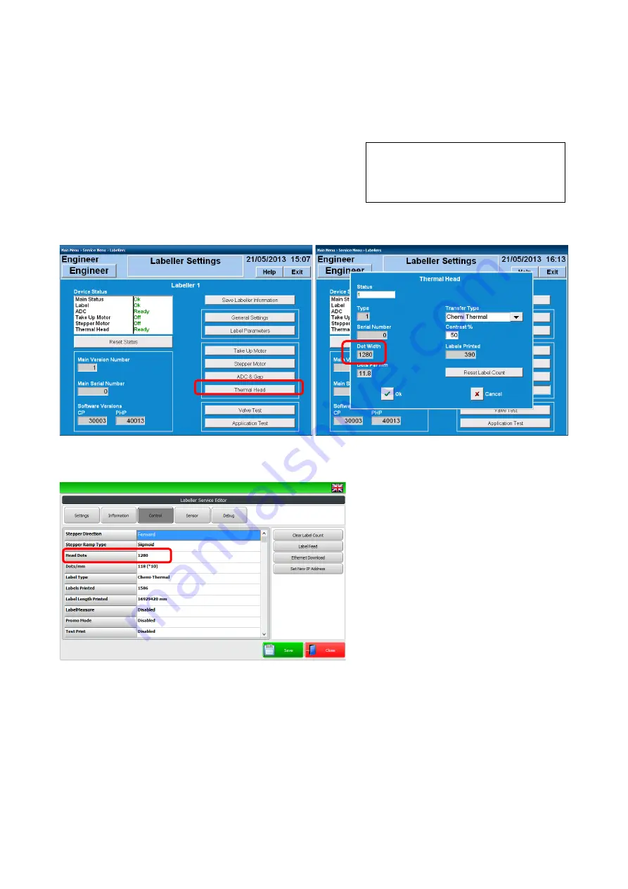
 Changing thermal head size


If the thermal head size on the labeller is to be changed, a setting in the Console or Worldview software 
needs to be changed.


This setting specifies the number of dots across the thermal 
head.


For 700 console software 

go to: Service menu / Labellers and select the thermal head option


For Worldview software 

go to: Service menu / Labeller setup / Service / Control 

-

 head dots


Setting for 108mm head is 1280


 Setting for 80mm head is 960


On the screen displaying the value, touch the     
figures under 

Dot width

’ 

(for console) or next 

to 

Head dots

’ 

for Worldview


80mm head = 960


108mm head = 1280


Enter the required value, touch 

ok

’ / 

Save 

and exit to the operation screen.


This value change is required so the text and         
information on the label format is centralised 
to the new size thermal head.


Important: only use the specified values given in this instructions for the Digi  

Europe supplied 108mm & 80mm thermal head, no other value should be used.


NOTE: if changing the thermal head size on a Signature labeller, the thermal head carrier plate will need 
to be changed or modified as the location pins are in different positions for the 80mm & 108mm thermal 
head 

-

 refer to information on page 4

-

57


Содержание HI-700HS

Страница 1: ...HI 700HS service manual Issue 2 06 2020 HI 700HS Service manual...

Страница 2: ...nts for improvement be found in this publication please contact DIGI Europe Limited DIGI House Rookwood Way Haverhill Suffolk CB9 8DG England Telephone 44 1440 712176 DIGI Technical Support service uk...

Страница 3: ...sport packaging Classic labeller 1 21 Loading labels Signature top labeller 1 22 Loading labels Classic labeller 1 26 2 Component parts The weigh station electrical cabinet 2 2 PC main board type LV 6...

Страница 4: ...4 3 Conveyor belt replacement 4 4 Conveyor strip down for roller drive belt tensioner replacement 4 6 Conveyor re assembly motor pulley grub screw location 4 10 Re assembly of conveyor 4 11 Setting dr...

Страница 5: ...box 4 89 HS blow applicator set up 4 90 Base labeller belt applicator 4 100 Labeller changing thermal head size 4 103 Labeller Signature Change label reel to centralizer type 4 104 Fit web centralizer...

Страница 6: ...1 6 Maintenance schedule Maintenance schedule introduction 6 2 All conveyors 6 3 Scale 6 4 Labeller 6 5 Label applicator 6 6 Base label applicator 6 7 Side label applicator 6 7 Labeller lifting gear 6...

Страница 7: ...8 3 Option fit parts Keyence barcode scanner 8 3 Conveyor belts 8 4 Conveyor parts 8 5 Labeller Signature type 8 6 Labeller Classic type 8 6 9 finger touch applicator for Signature labeller 8 7 Belt a...

Страница 8: ...servo indexer connection 1 13 Option part Barcode scanner Keyence 1 14 Option part LA 3600 inhibit label apply connection 1 15 Outfeed conveyor connection 1 16 Removal of conveyor 1 17 Load cell trans...

Страница 9: ...e The machine below is a HI 700HS right to left flow direction with top labeller Touch screen 12 or 15 Option part power pack guides Pack sensors Signature Labeller with touch air box or HS blow appli...

Страница 10: ...achine is protected from environmental conditions by a protective plastic cover Damage in Transit Ensure that the crate is not damaged Any damage in transit should be reported to the appropriate shipp...

Страница 11: ...d to current standards and fitted with a three conductor power lead It is essential that the power lead earth conductor be connected to a good and proper earth point which is also used for adjacent an...

Страница 12: ...ts will be stopped in this operation the PC software will remain on and accumulated information will not be lost When the emergency has been rectified and the machine is safe to switch on again the em...

Страница 13: ...wn to stop it moving on the pallet Protect the load cell by placing the transit screw and discs in position and support the labeller Protect the machine from environmental conditions and then move on...

Страница 14: ...Refer to the user manual for information on inputting programmable data such as plus label formats Note when programming the fields for printing it is important to note that under weights measures ap...

Страница 15: ...0 Hz or 105 115 V AC at 60 Hz depending on machine version and country Circuit breaker The machine is fitted with a miniature circuit breaker great care should be taken to ensure that the live phase c...

Страница 16: ...eplace labeller onto the arm as follows Remove the end plate and the two M8 cap head screws Slide the labeller on to the labeller arm Refit the two M8 screws into the labeller arm and the end plate Wi...

Страница 17: ...the electrical cabinet under the labeller outfeed conveyor Feed the conduit into the cabinet through the rear cable gland Cables and air pipe inside labeller conduit Air pipe to the air regulator Eth...

Страница 18: ...the four available ports Mains power connect the mains lead wires to the terminal positions shown above Brown live Blue neutral Yellow green earth Power lift connections 24v type connect the power lif...

Страница 19: ...ted to the rear of the labeller electrical cabinet Connect multi pin connector to position marked IN Terminal plug Connect Ethernet to position marked 1 Termination plug if the machine has one labelle...

Страница 20: ...ectrical cabinet using the multi pin connection on the side of the HI cabinet Also plug in the infeed sensor Plug the multi pin plug into the socket in the side of the HI electrical cabinet Ensure the...

Страница 21: ...tor connection Trigger sensor for barcode scanner The sensor to trigger the scanner is situated at the end of the outfeed conveyor As standard this sensor is the Wenglor type therefore if sensitivity...

Страница 22: ...his installation the reject signal REJ 1 2 or 3 will be connected to a relay in the HI cabinet before going onto the LA 3600 The cable that comes from the LA 3600 is connected to the relay at Relay po...

Страница 23: ...pin connector for the outfeed conveyor motor which needs connecting to the 8 pin connector from the electrical box The connector will be mounted on the rear side frame of the outfeed conveyor Line up...

Страница 24: ...rect gap to act as limit stop screws in the up direction The conveyor can now be remove from the machine 1 To gain access to these screws remove the conveyor for the scale Remove conveyor by releasing...

Страница 25: ...l from its transit setting The transit screws are at each end of the scale unit circled left Carry out the process below for both screws Loosen the nut under the bracket down to the lower nut Check th...

Страница 26: ...t on the load cell also add to this the scale capacity e g 3kg Turn each screw out until the head of the screw touches the underside of the scale frame Back each screw off so there is a minimal gap Fo...

Страница 27: ...d then turn the rotary power switch on the front of the control box 90 anti clockwise Note up down power lift buttons these buttons may be place on the labeller electrical cabinet if the HI HS is a pl...

Страница 28: ...buttons will be on the labeller electrical box for plug play type connection For labeller back forward position rotation loosen the locking handle on the top and or the side of the horizontal bar sli...

Страница 29: ...it central on the label roll shaft and when fed through the thermal head the centre line of the labels will be central on the thermal head If fitted with the optional label centralizer with labels wil...

Страница 30: ...this point and remove labels from backing paper to allow threading to final position take up spool Ensure when the backing paper is returned under the print area it runs behind the blow bar Feed back...

Страница 31: ...ls in the same way as the outside wound labels Important note if using inside wound labels If all labels to be used are going to be inside wound it is recommended the brake belt in the rear of the lab...

Страница 32: ...ding to manually adjust the back plate reel as for a standard reel assembly Signature labeller fitted with centralizer option Holding the rear reel unclip the front reel by turn it anticlockwise With...

Страница 33: ...bels follow the route shown on the diagram and details below Check labels are inside or outside wound and load accordingly Adjust rear spool position to allow centre of labels to run through the centr...

Страница 34: ...through the label gap sensor and between thermal head and platen roller Ensure backing paper is fed behind blow bar Open the drive pinch rollers and place backing paper around the drive roller Use la...

Страница 35: ...Conveyors HS type 2 27 HS servo infeed assembly 2 31 Labeller electrical control cabinet 2 35 Load cell 2 37 Touch screen 12 1 2 39 Touch screen 15 2 42 Labeller Signature 2 43 Classic type 2 44 Ther...

Страница 36: ...nnections are listed below Rear of cabinet 1 2 3 4 5 6 7 8 9 10 11 12 13 14 15 16 17 18 19 20 21 22 Cabinet right side Cabinet left side 23 24 25 26 1 Infeed Motor 2 Scale Motor 3 Outfeed Motor 4 SubI...

Страница 37: ...SU CPM2C PA201 10 Battery 12V 1 2amp 11 Hard drive SSD programmed see note 12 PC main board LV 67P 13 Pico UPS 100 14 Ethernet 5 port switch 15 Mains filter for 240v machine or Mains filter for 110v m...

Страница 38: ...Pentium N3710 1 6Ghz Memory 4Gb DDR3 Serial ports for PLC ADC Hard drive connection ATX Screen connection PC processor Launch button connection LAN interface labeller DC in COM 3 4 see next page Scree...

Страница 39: ...ND 6 DSR 7 RTS 8 CTS 9 Set by JP2 10 Key COM 1 RS 232 DB9 connector COM 2 RS 232 422 485 DB9 connector Pin Signal Pin Signal 1 DCD 422TX 485 2 RXD 422TX 485 3 TXD 422RX 4 DTR 422RX 5 GND 6 DSR 7 RTS 8...

Страница 40: ...ce manual 2 component parts 2 6 Issue 1 02 2020 JCSEL1 JCSEL2 For configure COM2 communication mode Function JCSEL1 JCSEL2 RS232 RS485 RS422 JCSEL1 JCSEL2 JP1 JP2 PC main board Type LV 67P COM port 2...

Страница 41: ...h Sata type connection The hard drive holds the Windows embedded standard image the console or Worldview operation software and programmed data such as plu s label formats etc Note any weighing calibr...

Страница 42: ...oard charge voltage approx 15v for Pico UPS 100 The battery is used if a sudden power failure occurs The power in the battery is used to safely shut down the PC NOTE In normal operation the machine sh...

Страница 43: ...s voltage to the PC main board 15 8v The input voltage 240v AC is supplied from the terminal rail connection LS75 15 UPS board 15 8v output from PSU 13 5 to 15v output from UPS to battery via relay ba...

Страница 44: ...r the un interruptible power supply UPS The board has a 15 8v input from the power supply LS75 15 and outputs 15 8v to the PC The board also supplies a charging voltage to the battery via a relay of 1...

Страница 45: ...l labeller printer that are to be connected to the machine The switch is supplied a voltage of 5v from the PC main board Ethernet connection from main board Refer to p2 4 for LAN connection point Conn...

Страница 46: ...tery UPS board is connected to the relay at positions 14 11 and is switched to this if the 5v supply fails Relay 2 is used to switch on the green LED on the front of the touch screen assembly The rela...

Страница 47: ...ction on power supply CN2 Connection of 5v and 9v to A D Mains power into power supply Along the top of the board is four LED s When lit these indicate 5v and 9v sup plied from the board Pin 1 5V ADC...

Страница 48: ...ngs are controlled within the machines software Worldview or Console The metrological settings are stored on this board not the hard drive To gain entry to the A D settings within the service menu it...

Страница 49: ...wer supply connection Serial connector 9way D type connects to main board at COM port 2 Connection to pack sensor circuit from PLC A D Security switch See electrical diagrams for full details of conne...

Страница 50: ...ctor motor drivers and conveyor stop start circuit Refer to electrical drawing for exact route of connections Output voltage 24v to motor drivers contactor conveyor stop start circuit Mains power in T...

Страница 51: ...output signals to and from various parts of the machine E G pack sensors conveyor speed reject signal PA201 power unit PLC unit CPM2C MAD11 Analogue unit PA201Power unit Refer to the electrical drawi...

Страница 52: ...unit has indication lights on its front display to indicate the input outputs that are happening at the given time 00 Sensor 1 infeed 01 Sensor 2 scale 02 Emergency stop switch 03 Sensor 2 scale 04 Se...

Страница 53: ...being slowest speed 5v being max speed This voltage is connected to each motor speed control board at VRM black v and VRL orange v To Motor speed control boards Black to VRM v Orange to VRL v Black Bl...

Страница 54: ...lds the outfeed motor driver s Note on board speed potentiometer This should not be adjusted as conveyor speeds are initially set by an external potentiometer and then controlled from the machines sof...

Страница 55: ...HI 700HS service manual 2 component parts 2 21 Issue 1 02 2020 Motor driver board Purple Blue Black Black Red NC NC NC NC...

Страница 56: ...ve the outfeeds All of these potentiometers do not require any adjustment for installation and speed setting of the machine these potentiometers are factory set and locked to their setting Component r...

Страница 57: ...ors is protected by a fuse rated at 315mA The location of this is show below FOR SAFETY Ensure the power plug is removed from the power outlet before replacing fuse and or operating MCB Circuit breake...

Страница 58: ...e is plugged into one of the USB ports on the PC main board and must remain in place to obtain correct operation of the machine Worldview software Machines running Worldview software will have a speci...

Страница 59: ...may be a single Servo drive conveyor only or conveyor and side drives 3 servo unit Specific programmed chip for indexer operation CN1 CN2 CN3 CN4 CN5 CN8 Connector Pins Operation CN1 3 Power to board...

Страница 60: ...to operate the single white brown wires teach wire connection as shown above needs to be disconnected using the 2 way Molex plug Once the teach operation has been completed the Molex plug can be reco...

Страница 61: ...r wire retaining clip shown above right is clipped back into position on the bracket and non of the motor wire is touching the upper load cell area For all conveyors locate the conveyor onto the pins...

Страница 62: ...ntify the last digit indicates ratio DC motor 50W except 400mm scale which is 30W Idler roller Conveyor belt tension screws see service section for adjustment Drive roller Conveyor location block at e...

Страница 63: ...n to the standard HS conveyor with the addition of Cable motor clip Conveyor belt guide 400mm has 30W motor instead of 50W Cable motor clip Conveyor belt guide this should be adjusted to allow the con...

Страница 64: ...ting two sets of conveyors It is removed from the machine in the same way as other HS type conveyors 1 Remove conveyor by releasing the four side clip 2 Inside the BL cabinet unclip motor connection t...

Страница 65: ...o driven conveyor or with the addition of servo driven side guides Assembly with single servo infeed conveyor Addition of servo driven side guides Adjustment of infeed guides Standard guides Loosen th...

Страница 66: ...ips 3 Lift conveyor to access the servo motor cable connection to the servo motor 4 Un screw the connector at the end of the orange cable to unplug the cable from the motor 2 3 4 5 5 lift conveyor out...

Страница 67: ...plug into the mains power supply and turn the isolator switch on The power indicator lamp will illuminate green The Ethernet socket at the rear of the electrical cabinet is use to program the servo m...

Страница 68: ...rive 6 5v power supply for Ethernet switch power 7 Ethernet switch connection point between servo unit and rear RJ45 socket for programming Servo unit 8 Cooling fans x2 Identifying the parts inside th...

Страница 69: ...ovement arrow up white button arrow down black button Press required button to move height of labeller up down to conveyor deck 5 Multi pin connection plug in the cable from the weigh station electric...

Страница 70: ...ower to Ethernet switch 3 Ethernet switch labeller connection 4 Motor driver board control to conveyor motors 5 Relay safety e stop circuit 6 Mains filter 7 MCB 8 Potentiometer factory setting of thes...

Страница 71: ...and a machine capacity of 12kg for the 30kg load cell The load cell is supplied with a cable gland fixing plate and connecting plug fitted to the cable This assembly aids replacing this component if r...

Страница 72: ...R0 359 54 Reference excit Voltage U ref 5v Norm range of excit Volt BU 1 12v Max excitation voltage 15v Mounting screw tightening torque 14Nm Wiring of load cell plug for connection to A D Pin 1 green...

Страница 73: ...for starting PC rear of screen assembly LED screen With touch panel below Electronic board assy USB touch PCB To gain access to the rear of the screen assembly the screen surround will need to be rem...

Страница 74: ...LED screen for fitment with LV 67P main PC board The LED screen is mounted behind the touch panel and has connections to the main pc board With the LED screen removed the touch panel can be seen Note...

Страница 75: ...PCB links the touch panel to the PC main board The input output signals to from the touch screen are processed though this board and onto the PC main board CN2 Connection to PC main board LV 67P via...

Страница 76: ...icator Launch button for starting PC is on the underside of the screen enclosure USB port mounted on the side of the enclosure with protective sealing cap Turn the two cam latches to release the rear...

Страница 77: ...ont and side applicator systems can also be fitted to the Signature labeller 9 finger Touch multi jet air box or HS blow applicator Backing paper take up Drive pinch rollers Label gap sensor Thermal h...

Страница 78: ...touch applicator fitted Common parts exist between the Signature Classic labellers such as power supplies labeller board stepper motor take up motor thermal head 9 finger Touch applicator Thermal hea...

Страница 79: ...ry control and driver LSI which has the function of thermal historical control of the temperature power required for each head dot Classic labeller Parameter 80mm 108mm Effective print width 81 312mm...

Страница 80: ...surface of the strip will wear out and need to be replaced A worn or damaged wear strip can cause bad print Refer to the servicing section for details on replacing the wear strip silicone tube The wea...

Страница 81: ...e assembly If near edge printing is not required or the labeller is to used with thermal ribbon the platen roller kit option can be fitted To ensure good quality printing the platen roller should not...

Страница 82: ...heaters are fitted into the head assembly as standard There are two heaters which are connected to the 25v power supply via two Molex connectors in the rear of the labeller The thermal head heaters ar...

Страница 83: ...djustment of this jumper is not normally required Note the second set of jumpers J6 are not used There are three connections on the board to allow software updates onto the board This process can also...

Страница 84: ...ace board mounted The label gap sensor is connected to this board and its sensitivity can be adjusted via this board TR5 TR4 TR3 TR2 TR1 Trimmer pots TR1 iMark OP AMP gain TR2 Gap LED power TR3 Gap ph...

Страница 85: ...an earlier made Classic labeller the PSU fitted will be a different type The replacement will be the type shown above An additional bracket will be required the first time this PSU is fitted into the...

Страница 86: ...electrical cabinet To PL11 on labeller board 25v to pins 3 4 0v to pins 5 6 25v PSU Image from Signature labeller This PSU supplies 25v onto the labeller board which will then supply The thermal head...

Страница 87: ...et The output is Voltage 42v 0 3v Power output wattage 200w Rated current 4 2A NOTE The standard manufactures output voltage for this power supply is 48V The power supply is reset to 42V for this labe...

Страница 88: ...speed of the stepper motor is adjusted by changing the print speed for the selected plu The print speed range is 50 260mm sec Cassette labeller uses different stepper motor and the max for this is 200...

Страница 89: ...ol via a toothed belt and pulleys This motor is a 24v DC and obtains it power from the 25v PSU in the labeller The unit incorporates a gear box to obtain the required rotational speed The motor connec...

Страница 90: ...r Worldview software The gap to head distance setting is the distance the label gap sensor is from the thermal head The head to bar distance is the distance from thermal head to stripping bar edge Not...

Страница 91: ...hermal head pressure Signature labeller The pressure of the thermal head onto the label wear strip platen roller is controlled by a pneumatic cylinder The pressure this cylinder exerts is regulated by...

Страница 92: ...ir cylinder Inside the applicator unit there are two 24v fans to create an up flow of air to hold the label on the applicator shoe Applicator position The position of the applicator fitted to the Sign...

Страница 93: ...s mounted in the rear of the Signature labeller to control the air flow of the blow If the blow bar is too weak the label is not transferred to the receiver If the blow bar is too strong the label can...

Страница 94: ...20 Pneumatic connections The following is a diagram of the air valve connections within the touch applicator assembly The solenoid valves electrically connect to the labeller board at PL6 PL7 700 LABE...

Страница 95: ...to cover certain areas of the air jets This is to concentrate the air flow in a set area for different size labels The three sizes supplied with the machine are shown below To change the blanking plat...

Страница 96: ...ar cover to access the pneumatic for the applicator Blow bar air flow To aid good label placement onto the label receiver the blow bar should have a suitable air flow set and its air jet holes positio...

Страница 97: ...k Inwards towards applicator body reduces air holes Outwards extending blanking plates out of applicator body increase air holes On the underside of the applicator move the fan blanking plate in or ou...

Страница 98: ...HI 700HS service manual 2 component parts 2 64 Issue 1 02 2020 HS blow applicator Pneumatics...

Страница 99: ...nto the base of the pack The belts run at a fixed speed and are controlled by their own dc motor and motor driver unit NOTE the motor driver units in this labeller electrical cabinet look very similar...

Страница 100: ...At the required time the fingers are forced down through the receiver by the air cylinder for application onto the pack The operation of the up down movement of the air cylinder is made by an air valv...

Страница 101: ...eller touch applicator The following is a diagram of the air valve connections within the touch applicator assembly The solenoid valves electrically connect to the labeller board at PL6 PL7 5 2 VALVE...

Страница 102: ...nts Removal and cleaning of conveyor belts 3 2 Pack sensors 3 3 Cleaning the thermal head 3 4 Cleaning labeller drive and pressure rollers 3 6 Condition of wear strip platen roller Signature labeller...

Страница 103: ...cloth to avoid leaving fibrous deposits When top surface has been cleaned carefully push the conveyor belt to rotate it for cleaning the remainder of the belt Recommended cleaning solutions are dilute...

Страница 104: ...nted in the conveyor deck Ensure there is nothing blocking the sensing path e g no debris is resting in the conveyor where the reflector is If the machine has across the deck type mounted sensors the...

Страница 105: ...ning cycle Initially cleaning should be carried out every 2000 3000 labels Once the machine is power off including isolator open the thermal head assembly as shown above Place a clean Safesleeve Digi...

Страница 106: ...print head assembly back into position return the applicator back to the head assembly and latch into position Cleaning the thermal head Signature Classic labellers Lift the thermal head assembly by t...

Страница 107: ...for food industry applications Allow the rollers to dry before refitting the label roll paper Signature labeller Hinge the pressure roller away from the drive roller to gain access and remove the lab...

Страница 108: ...uld be checked for wear and or damage as this can affect the print quality Also check the roller surface is clean and the roller spins easily Note will not spin independently if back feed kit is fitte...

Страница 109: ...display Switch off and disconnect the machine from the mains electricity supply Wipe the control boxes and display using a soft lint free cloth moistened with warm dilute detergent NOTE Allow the surf...

Страница 110: ...base labeller re assembly important notes 4 22 Weighing Load cell 4 24 Load cell removal 4 28 Re assembly 4 30 Latch block and levelling pin 4 32 Re calibration of machine Worldview software 4 33 Re...

Страница 111: ...on 4 110 Central knob resistance adjustment 4 112 Labeller Signature fitting printer door 4 113 Side labelling applicator 4 119 Speed control of applicator 4 119 End stop cushioning 4 120 Air pressure...

Страница 112: ...ssembly or scale deck if scale conveyor Refer to section 1 installation or section 2 component parts for details on how to remove the conveyor from the machine Typical conveyor shown below 475mm long...

Страница 113: ...stments at the idler roller Using a ball end hex key place in slot in the side of the conveyor at the idler roller end Unscrew the hex head screw to move the idler roller back and releasing tension on...

Страница 114: ...refit the conveyor belts ensure the idler roller locates correctly into the idler roller plates check it can freely move in the slots The adjuster screw locates in the recess in the roller end both en...

Страница 115: ...eyor belts removed see previous two pages for this process the conveyor can be taken apart to replace required items Slide out the idler roller from its mounts Loosen the four screws holding the motor...

Страница 116: ...d bolts washers holding the drive belt in place 9 Loosen and remove the three screws retaining the drive roller bracket The drive roller can now be removed 10 Idler roller Drive roller If one or both...

Страница 117: ...belt for wear or damage and replace if needed 14 Remove the four screws and washers holding the motor gearhead in place to allow the assembly to be removed 15 Lift out motor gearhead assy Check condi...

Страница 118: ...crew on the side of the deck circled above to remove the guide assembly 18 The guide pulley or guide roller can be replaced as complete assembly This is advisable as each part is glued pressed togethe...

Страница 119: ...ft must have a grub screw in all four positions in the pulley Fit an M4x10 grub screw on the opposite side to the keyway fit M4x5 grub screws in the other three positions Use Loctite 243 The key suppl...

Страница 120: ...yet leave the motor assembly loose until roller is fitted to ensure correct tension for drive belt If roller is in place lift motor assembly to tension drive belt and tighten fixing screws 21 See not...

Страница 121: ...ng the drive roller brackets are not fully tight the position of the roller can be moved up down in relation to the deck Drive roller bracket Drive roller bracket A useful way to obtain the correct le...

Страница 122: ...ully tight the position of the roller can be moved up down in relation to the deck Roller Conveyor deck Straight edge A useful way to obtain the correct level of roller and conveyor deck is to place t...

Страница 123: ...e strip or strips should be replaced The strips are evenly spaced across the width of the conveyor deck and number of strips will depend on the conveyor width Refer to the HI HS parts manual for amoun...

Страница 124: ...motor instead of the usual DC motor and gearhead assembly For all servicing items such as conveyor belts replacement roller replacement drive belt and anti friction tape replacement refer to the prev...

Страница 125: ...long and short sets of conveyor belts with a toothed drive belt system linking the two conveyors On re assembly of this conveyor refer to additional assembly information tips on pages 4 22 to 4 26 to...

Страница 126: ...ove the joining bar Lift out the idler roller bar from the bush Slide the short and long conveyor belts off of the conveyor assembly Note the idler rollers sit in the idler roller plates at the end of...

Страница 127: ...of roller assembly check for smooth rotation replace if required Idler roller assembly 718 0009 x2 Drive assembly The two drive rollers are driven by the single motor and gearhead assembly To gain acc...

Страница 128: ...is in the assembly the opposite way round to the other three head of bolt behind drive belt not the Nylock nut Pull motor assembly sideways to release belt tension Unscrew and remove the four screws...

Страница 129: ...the tensioner use Loctite 641 between post and bearing and between bearing and sleeve Remove the four counter sunk screws holding the drive bearing plate Remove drive bearing plate The toothed drive...

Страница 130: ...all parts and replace any worn or damaged parts Removal of drive rollers Remove the screws holding the bearing block in place There are two bearing blocks one for each conveyor Remove the side catch b...

Страница 131: ...onveyor assembly On assembly Loctite is use on these rollers to secure in place Drive roller assembly 718 0014 Re assembly Important points to note On BL conveyor assemblies build before January 2020...

Страница 132: ...to sleeve and post into bearings Use circlip on post end to secure Drive belt plate Use Loctite 641 between plate bearings Ensure the flange bearings are placed in the plate the correct orientation Fl...

Страница 133: ...cut 720mm MM8 00030 c Tape 25mm UHMWpe cut 262mm MM8 00030 d Cut four strips of MM8 00030 c and stick to deck 710 0088 in positions show below Cut four strips of MM8 00030 d and stick to deck 710 0089...

Страница 134: ...r joining plate use Loctite 641 between bearing and block plate Idler roller plate correct orientation Slight adjustment position of the plate may be required on assembly with the roller in place ther...

Страница 135: ...o roller shaft use Loctite 641 between shaft and bearing NOTE Do not use plain washers only use spring washers in these positions Drive pulleys belt tension Use Loctite 243 on grub screws that secure...

Страница 136: ...emoving the load cell un plug the load cell from the ADC The cable cover plate can be unscrewed from the rear of the electrical cabinet and the load cell un bolded from the scale Cover plate fitted at...

Страница 137: ...2020 Load cell removal scale top frame removal 1 Unscrew and remove one of the transit over load stop screws 2 Loosen the two side screws 3 Unscrew and remove the two top screws 1 2 3 The top scale fr...

Страница 138: ...cell removal continued 1 Loosen the two side screws 2 Unscrew and remove the two screws located on the underside of the scale base bar 1 2 3 3 The load cell can be lifted from the scale base assembly...

Страница 139: ...16 screws and torque to 14nm Tighten side screws Apply Loctite 243 to side screw at final assembly remove each side screw in turn and apply Loctite 243 These screws to be tightened to Torque value of...

Страница 140: ...it the transit over load stop screw or screws if both were removed and set to the correct height for load cell protection see section 1 installation for details on this Once scale top is in position c...

Страница 141: ...y has been dis assembled fit grub screw loose at initial re assembly stage allowing latch block to rotate freely on pin tighten grub screw into pin groove after fitting assembly to scale top Loctite 2...

Страница 142: ...ale To start the calibration process of the scale touch Span Wait for the on screen instruction IMPORTANT This operation to be undertaken by the distributor or other qualified persons using traceable...

Страница 143: ...s are required for this process but as with calibration ensure scale area is clear of any debris Touch the zero button and follow the on screen instructions Clear scale Ensure scale is completely clea...

Страница 144: ...weight enter the weight in grams of the weight used to calibrate the scale Capacity The maximum capacity of the scale Interval The scale interval in mg Re calibrate Zero This re zero function may be...

Страница 145: ...t for the on screen instruction to Clear scale ensure scale is completely clean with nothing resting on it Load span weight place the pre determined calibration weight on the scale Span complete this...

Страница 146: ...Un plug 9 way D type connector plugged into main board LV 67 P main board Un plug 3 way Molex plug from main wiring loom Un screw the 4 mounting screws and remove ADC unit form machine Replace with n...

Страница 147: ...i e capacity details calibration and sub span data is stored on the IC marked IC19 ADC security switch location Data storage on ADC board Set Security switch No 1 to the OFF position to allow entry t...

Страница 148: ...AME VALUE THAT IS TYPED IN FOR THE CHOSEN PARAMETER Press OK and Save on exit shut machine down and restart to enable scale The scale will now function check all calibration for correct weighing This...

Страница 149: ...o allow entry see page 4 38 for location Message security switch must be turned OFF Go to ADC settings in the service scale screen select a setting any value will be ok to select but make sure the val...

Страница 150: ...lower right side inside the electrical cabinet The following describes the removal replacement of the hard drive Hard drive Unscrew the two screws holding the mounting bracket in place Lift the hard d...

Страница 151: ...et Ensure correct orientation of new hard drive in bracket and reuse the four screws to secure The solid state type hard drive has the connection as shown left Sata When refitting the hard drive into...

Страница 152: ...s from rapid to slow blinking In this mode slow blinking the teach in mode type can be selected By pressing the teach button again the mode will be changed 1 blink 2 blinks etc After the button has no...

Страница 153: ...emoved from the screen surround Peel the grey facia from the metal surround to access the 12 cap head screws Remove the 12 screws around the edge of the surround NOTE it may be easier to unplug releva...

Страница 154: ...nplug the touch panel ribbon cable from the USB touch PCB Note there is normally a piece of black tape over the connector peel back tape to un clip ribbon cable from board The LCD assembly can now be...

Страница 155: ...no 563 153 C2 Ensure a new seal is obtained and fitted to the replacement touch panel Seal on front side of touch panel to seal against the fascia 560 781 C1 Important notes for fitting seal Ensure wh...

Страница 156: ...screen replacement If the LED screen needs to be replaced follow the above dismantling procedure but there is no need to remove the touch panel from the outer surround Once the LED screen is removed...

Страница 157: ...rated With the machine switched on exit to Windows level Go to the Windows icon at the bottom left of the screen Select the Calibrate icon Follow the on screen instructions Please touch the centre of...

Страница 158: ...gain access to the screen assembly remove the 12 hex head screws around the edge of the rear cover Important when removing the screws support the front assembly screen to ensure this does not fall whe...

Страница 159: ...ear metal frame The screen assembly can be lifted clear of the fascia If required the metal mounting frame and insulating support can be removed from the front fascia To do this remove the 12 plastic...

Страница 160: ...panel combined The touch panel interface board is also part of the same assembly when required as a spare part To remove it from the rear metal frame disconnect the ribbon cable connected to the inte...

Страница 161: ...switched on exit to Windows level On the desk top click on the icon eGalaxTouch On the eGalaxTouch USB Controller screen select the Tools tab The required calibration can be selected When calibration...

Страница 162: ...HS style screen The 15 HS style screen assembly can be opened at the rear to access the component parts of the assembly At the rear of the screen assembly use the cam latch key to turn the two cam loc...

Страница 163: ...t for display 710 0281 1 3 Assy USB touch screen PCB B569 185 1 4 Assy 15 touch screen gasket 718 0055 1 5 Locator 15 touch screen 710 0279 1 6 Clamp 15 touch screen 710 0280 1 7 M3x6 Sems pozi pan sc...

Страница 164: ...roller 701 0051 option fit Pozi head Cap head M3 0 7 1 2 M4 2 1 2 6 M5 4 5 6 0 M6 13 5 Signature labeller Torque wrench settings Nm Thermal head pneumatic pressure Standard values are 80mm wide therma...

Страница 165: ...er to the labeller must be turned off Open the applicator latch and hinge the applicator away from the print head area Turn the black knob to open the print head area Un screw the two clamping screws...

Страница 166: ...d The locating pins in the carrier plate are in different positions for a 80mm head and a 108mm head Ensure correct carrier plate is used for head size Re connect the two cables to the thermal head Re...

Страница 167: ...eld in place by the near edge stripping bar clamping it between that and the near edge support bar Underneath the wear strip is a silicone tube mounted into the stripping bar this may also need replac...

Страница 168: ...p can be lifted off the rear pins on the stripping bar and replaced with a new one Check the condition of the silicone tube and replace if required The silicone tube should be smooth along its length...

Страница 169: ...ndentation the print quality will deteriorate To replace the platen roller Unscrew the outer c sunk screw holding the stripping bar Unscrew the two c sunk screws holding the platen roller front block...

Страница 170: ...ufficient for the required print but not excessive as to cause premature wear to the thermal head wear strip silicone tube The air pressure can be adjusted by an air regulator fitted in the rear of th...

Страница 171: ...izontal adjustment on the two adjuster screws NOTE before setting the head mount plate position the thermal head horizontal position should be set using the two adjuster screws to its default position...

Страница 172: ...up position can be set Loosen the four hex head screws holding the mounting plate to the back plate Slide the assembly back forward to obtain the correct position of thermal head at stripping bar see...

Страница 173: ...head set up position can be set Loosen the four hex head screws holding the mounting plate to the back plate Slide the assembly back forward to obtain the correct position of thermal head on platen ro...

Страница 174: ...ion Head set up position continued When moving the mounting plate back forward the position of the thermal head to the stripping bar is set The front edge of the thermal head should be in line with th...

Страница 175: ...ed or the print is poor the two adjuster screws can be adjusted for a fine adjustment of the horizontal thermal head position Turn each adjuster screw to obtain the required print quality Typical poor...

Страница 176: ...he correct gap fold two labels with backing paper together Place under the thermal head between head and wear strip or platen roller Ensure head is in its down position and the air supply is off Pulli...

Страница 177: ...position With the thermal head in its locked down position loosen the large nut at the top of the air cylinder Screw the air cylinder down until it just touches the head adjustment block then back off...

Страница 178: ...reshold value The sensor can be set to read in different modes standard default threshold In threshold mode the gap sensor value must change by a least the value set in the gap threshold setting Refer...

Страница 179: ...or With a solid white label typical values can be Label in sensor 2400 Gap in sensor 240 Nothing in sensor 150 2 Change jumper J5 position For Signature labeller with additional sensor I F board this...

Страница 180: ...ng colours check whole label to determine where the highest value is The max value for sensor is 4095 adjust so that the value is still changing approx 3800 With the sensor set as above when the senso...

Страница 181: ...e High speed classic for 2nd stage and classic labeller types Labeller software after this version will have each labeller type listed for selection 1 IP address setting Ensure the rotary switch is se...

Страница 182: ...tronic board The classic labeller uses the same electronic board as the Signature labeller but does not use the sensor I F board The orientation of the this board in the classic labeller is as shown b...

Страница 183: ...achieves Default setting for motor torque The default setting for the trim pot on the labeller board is 2 3 towards the maximum Fully anticlockwise being minimum Fully clockwise being maximum If the...

Страница 184: ...Adjustments can be made to this assembly to obtain the correct suitable working of the brake Correct position for brake arm When looking at the front of the labeller with no load on the brake arm it...

Страница 185: ...down on the brake arm will make the brake pivot boss rotate and release belt tension around the brake boss This will allow the reel shaft to rotate The grip of the belt braking force can be increased...

Страница 186: ...lease of the brake Note if running a mixture of outside inside wound labels it is best to continue to use the outside wound setup but ensure the part 701 0195 support brake belt is fitted This part is...

Страница 187: ...hanged to a R L inside wound setup When changing to inside wound setup ensure part 701 0195 is fitted Slide belt off boss Then Unscrew and remove from mounting plate the brake adjuster boss Unscrew th...

Страница 188: ...unting bracket Unscrew the belt from the brake adjuster boss and refit in the orientation shown left NOTE use Loctite 222 on screw thread Refit the brake adjuster boss to the mounting plate in the new...

Страница 189: ...n this screen the software versions installed are listed How to update software There are two possible methods depending on the version of labeller software already installed Method 1 If the PHP label...

Страница 190: ...Labeller set up Service control select Ethernet download A screen to browse to the location of the new software will now be displayed Browse to the location of the new BIN file Select the file and pre...

Страница 191: ...cation Before starting this process ensure the new software is available on external memory device or stored in a location which can be browsed to The file will be a BIN type for example Console softw...

Страница 192: ...able is connected A message will appear while the software is being updated Ensure power is not interrupted while this is in progress When the download of software is complete a message will appear Sh...

Страница 193: ...module board to PL19 PL15 Switch on the isolator switch of the machine NOTE do not launch the machine rear screen button With the isolator on wait for the software to be loaded onto the board An indic...

Страница 194: ...enu labeller settings is correct Check the labeller can carry out a label feed operation If this does not work the up load of the 2nd part of the soft ware has not been successful Return to the proces...

Страница 195: ...06 2020 Method 2 using plug in module continued Updating the labeller board software is the same process for 2nd stage labeller classic labeller The only difference is the board orientation Orientatio...

Страница 196: ...cement onto the applicator shoe Adjustment of the restrictor may be required depending label shape and size Remove the rear labeller cover and adjust this restrictor to change the air flow through the...

Страница 197: ...ger touch applicator normally only cassette labellers there are two types of finger pads plus the single blue banded vacuum finger When replacing ensure correct type of finger is fitted General care o...

Страница 198: ...at are supplied with the air box refer to section 2 component parts These shutters will control the air flow from different jets so different size labels can be controlled The air jet nozzles are scre...

Страница 199: ...the label therefore have a non sticky corner Place the label on the receiver using the folded corner to obtain correct alignment The following setup procedures are carried out with the machine labelle...

Страница 200: ...ar disc to suit label width so that the labels sit central The distance from the rear disc to the mid point of the spring core should be half the label roll width Note Datum distance the distance from...

Страница 201: ...n using the HS blow applicator is a dedicated one for this applicator see below Centre line of label path and applicator receiver Blow bar hole positions Remove rear applicator cover to gain access to...

Страница 202: ...he label where it is in the deepest part of the concave shape of the applicator receiver HS blow applicator setup continued Applicator height Set the height of the receiver plate in relation to the st...

Страница 203: ...or height Remove the rear cover 4 screws Loosen applicator mounting screws circled below Move the applicator up or down to obtain the correct height Ensure the applicator is kept level measure left an...

Страница 204: ...abel receiver Gap Check thermal head movement With the correct gap size set as above check the thermal head can be lifted and lowered without it touching the label applicator To adjust gap size see be...

Страница 205: ...y reduces air holes Outwards extending blanking plates out of applicator body increase air holes On the underside of the applicator move the fan blanking plate in or out to change the size of area in...

Страница 206: ...t should not be too long more than 60ms as excess air can create label placement inaccuracy Note if any changes are made on this page ensure the button is pressed to store new setting before using the...

Страница 207: ...test are shown left in red circle Select General settings Application type Air box Note Head to bar gap to head distances should already be set to ob tain the correct stop position of the label at the...

Страница 208: ...e Select a label format file to enable these options Select appropriate label format file Press Application trigger interval default 1000 Set value as required lower value faster operation Start appli...

Страница 209: ...e suction of air to hold the label onto the belts is made by four 24v DC fans within the assembly of the applicator To carry out any maintenance on the belt applicator assembly the complete assembly n...

Страница 210: ...side of the labeller cabinet and remove the com plete applicator assembly The assembly can now be disassembled to carry out required maintenance The fans are easily accessible from the underside of th...

Страница 211: ...f the roller and the centre shaft is the same for both rollers To tension the four belts loosen the mounting screws holding the motor gearhead and move motor geadhead assembly up down to obtain the de...

Страница 212: ...creen displaying the value touch the figures under Dot width for console or next to Head dots for Worldview 80mm head 960 108mm head 1280 Enter the required value touch ok Save and exit to the operati...

Страница 213: ...cribes the process to change to this type of reel There are two assemblies for the centralizer Label centralizer 707 0015 A Web centralizer 707 0008 A In the rear of the labeller the brake arm assembl...

Страница 214: ...the boss Remove the outer circlip and the shim Remove the outer bearing Note this is normally held in place with Loctite 222 which is a low strength locking compound therefore the bearing should push...

Страница 215: ...the labeller fit the inner circlip Clean bearing surface of any old locking compound Re fit the bearing To secure in place use Loctite 222 Re fit brake boss and tighten set screws Re tighten set scre...

Страница 216: ...Change label reel to centralizer type continued If the brake arm has been loosened from the shaft reposition arm Follow guide for this on page 4 75 Fit Web centralizer Remove the standard web guide b...

Страница 217: ...ntinued If fitted unscrew the end screw holding the spacer to the shaft Fit the Web centralizer to the front of the labeller noting the spacer fits between assembly and back plate Secure with screw pr...

Страница 218: ...centred by the reels it is important the reels are correctly adjusted for centralization For fine adjustment of label reel position loosen the two set screws Moving the end centralizing knob back and...

Страница 219: ...e or tight the height position of the ball plungers can be adjusted With the front reel disc remove the ball plungers can be seen Using the three holes in the back of this assembly and a flat blade an...

Страница 220: ...ntinued Loosen the set screw which secures each pin Using the M3 screw pull out the two centralizer guide pins The front ring can now be removed from the central shaft Adjust ball plungers as required...

Страница 221: ...y not keep its adjustment If too tight it may be difficult to turn Loosen the set screw recessed in the knob and remove the knob The central shaft and locknut are now visible Using a spanner to hold t...

Страница 222: ...d Fit ball catch MM9 00215 to catch bracket 701 0143 A Use two M4x10 c sunk screws plus M4 nut with spring plain washers Fit catch bracket to side bracket 701 0141 B note position depending on L R or...

Страница 223: ...lock nut with plain washer Note the fixing holes in the hinge bracket are slotted fix hinges in upper most position Fit hinge cover to screws Fit ball catch striker to striker bracket 701 0144 A Use t...

Страница 224: ...tting to labeller Remove black blanking plug Remove the cap head screw top one only For the side where the door hinge bracket is to fitted remove the three screws which secure the back plate and label...

Страница 225: ...e bracket and the labeller back plate Secure in place with M6x20 caphead screw plus M6 nut spring plain washers at the rear of the back plate Re fit the fan bracket once nut is tightened At the rear o...

Страница 226: ...me together circled left Fit the side bracket noting orientation for L R or R L the ball catch will be in the lower position Re fit the two screws to secure the bracket Fit side support 701 0145 A bet...

Страница 227: ...S service manual 4 servicing 4 118 Issue 2 06 2020 Signature labeller fit printer door continued Fitting to labeller continued Check alignment of ball catch to striker and adjust striker position as r...

Страница 228: ...matics At the required time the double acting air cylinder moves the shoe to the package When the shoe touches the package the spring loaded action of the shoe pushes back to activate a proximity sens...

Страница 229: ...cushion the end stop With the top cover removed the air cylinder is visible Using a small hex key the end of the cylinder turn the screw to adjust amount of cushioning Air pressure vacuum adjustment...

Страница 230: ...the holes are covered the vacuum will feed down the slotted parts to maintain a vacuum on the area of the shoe covered by the label Refer to previous page for vacuum pressure adjust ment Holes for va...

Страница 231: ...tion is detected by the proximity sensor which in turn retracts the cylinder Cylinder movement Applicator shoe movement Shoe will be pushed back against spring pressure to activate the proximity senso...

Страница 232: ...on has the same operation and setting as a standard applicator Set value as required for correct timing of label application to pack Application time the length of time the applicator arm stay out Typ...

Страница 233: ...HI 700HS service manual 4 servicing 4 124 Issue 2 06 2020 Servicing adjustments Software settings continued Valve test To test applicator arm movement use the Spare 1 option in the valve test list...

Страница 234: ...eller and side frame unscrew remove the screw in the support plate Unscrew remove the 4 screws in the rear post circled in red below NOTE do not remove the central screw Central screw This screw acts...

Страница 235: ...er Standard Signature labeller servicing and adjustments apply refer to relevant section in manual for details Blow bar value restrictor position The valve and in line restrictor are mounted inside th...

Страница 236: ...e the travel stop clamp is secure and tight If moving labeller higher the clamps will move away from the travel stop If moving labeller lower first check clamps are tight then loosen travel stop and m...

Страница 237: ...ng labeller up observe important note on previous page Loosen the upper and lower clamps Note an assistant may be required for this operation Lift labeller to desired height while in position tighten...

Страница 238: ...HI 700HS service manual 4 servicing 4 129 Issue 2 06 2020 Side labeller applicator Pneumatics...

Страница 239: ...HI 700HS service manual 4 servicing 4 130 Issue 2 06 2020 Classic labeller servicing Thermal head 80mm 565 743 Thermal head 108mm EX0 00030 Platen roller 505 129...

Страница 240: ...rmal head to its upper position by turning the black hand lever Using a cross head screw driver un screw the single screw holding the thermal head and its brack et in place Carefully withdraw the ther...

Страница 241: ...ng screws holding the bracket to the head The bracket is reused on the new thermal head Replace bracket onto the new thermal head Re connect the power and ribbon cables Re fit the head into the machin...

Страница 242: ...f the roller has any missing or torn parts in the rubber material or has worn a central groove where the paper always runs then it will need replacing Lift up the thermal head by turning the black han...

Страница 243: ...oller is removed Check bearing condition Check the platen roller bearing in the front bracket Refit platen roller ensuring the rear bearing is located correctly in the rear bracket Replace front brack...

Страница 244: ...roller Loosen the lock nuts and use the two brass screws to adjust the head position The ideal position is to have the line of printing elements of the thermal head in line with highest point of the p...

Страница 245: ...The pinch roller is sprung loaded against the drive roller To check the adjustment of pinch is correct place a piece of backing paper between the rollers and slowly pull to see if the paper slips wit...

Страница 246: ...ay wind too slow and therefore not take up all the paper A torque adjustment is possible on the labeller board Located at the top left classic labeller orientation is a board mounted potentiometer Adj...

Страница 247: ...k plate the central screw through the bearing Inspect belt for damage or wear If fitting a new motor fit original motor bracket to the new motor Check pulleys and central bearing for wear or damage re...

Страница 248: ...pper motor drive a toothed belt which then rotated the drive roller Check drive belt tension To adjust the tension of the toothed drive belt loosen the three screws at the front of the labeller back p...

Страница 249: ...ller Touch applicator 9 finger Remove the 3 screws holding the outer cover to access the fingers The touch finger pads can be replaced if they become spit damaged or worn Replace it by pulling the pad...

Страница 250: ...and lubricated the shafts with light oil Removal of touch finger Removal of a touch finger assembly may be required if it has become damaged or worn Using a pair of circlip pliers release the circlip...

Страница 251: ...he pre installed Omron Syswin program To upload a new program to the PLC follow the instructions below Exit the machine application software Worldview or Console touch the Windows icon bottom left of...

Страница 252: ...nnect function is ticked Select Mode If the program fails to connect to the PLC in the machine it may be due to the Com port setting in the Syswin program being incorrect To check go to Project Commun...

Страница 253: ...20 Select MONITOR Press OK Select Online again Select Download program to PLC SYSWIN safety warning message Select YES Download program to PLC message The item shown left should be marked with X Selec...

Страница 254: ...45 Issue 2 06 2020 The new program is now downloading When the program has finished downloading the message shown left is displayed Select YES The PLC program download is complete when this message is...

Страница 255: ...on point The machine uses a single extra sensor for all labellers on a lab station Possible combinations are Top Bottom Top and Bottom Twin top and bottom The sensor is connected to the labeller board...

Страница 256: ...l 4 servicing 4 147 Issue 2 06 2020 Select service 2 Setup the application position on each labeller so that the label is on the leading edge of the pack Click save after each change see pack image wi...

Страница 257: ...6 2020 Pack Pack and label edge the same 3 The Sensor can now be setup Navigate to the sensor tab 4 Enable Extra Sensors 5 Enable Extra Sensor leading edge if the label is being applied to the leading...

Страница 258: ...The pack should be labelled in the same place with no errors 9 If you find that the label is slightly out of position as shown below you may need to adjust the extra sensor distance slightly set in st...

Страница 259: ...Window MS set required value here for the extra sensor window Sensor distance mm set value here for distance scale deck to extra sensor see image on previous page Navigate to Service menu Labeller s...

Страница 260: ...the sensor is cut Troubleshoot Belt speed 120ppm Packs per second 120 60 2 Time between packs 1 2 0 5 seconds 500ms Extra Sensor Window 250 330ms Belt speed 160ppm Packs per second 160 60 2 667 Time...

Страница 261: ...englor teach wire connection can be found in the Scanner electrical box at the rear of the machine Console software settings Service menu internal external devices Control Serial port settings Serial...

Страница 262: ...ce Console software settings PLU editor Extra equipment Scanner control Bad scan 1 enable disable Label seen enable disable Operation screen If diagnostic is enabled see previous page this area displa...

Страница 263: ...r programming software is required Install this software onto the PC laptop that is to be connected to the scanner Serial connection to scanner for parameter setup download A serial lead RS232 is requ...

Страница 264: ...anges for the project file Option specify the communication parameters of the PC Connection update connect reconnect to the BL 1300 Options select this to display the page shown left Enter the serial...

Страница 265: ...ameter and barcode settings can now be defined If a previously configured setup has been saved this can be download to the scanner Use the to open a saved project file Browse to the location of the sa...

Страница 266: ...0HS service manual 4 servicing 4 157 Issue 2 06 2020 Select BL 1300_1 The selected project file settings are now displayed Select The connecting communication box will appear Setting parameters for BL...

Страница 267: ...20 Setting parameters for BL 1300 When the software has successfully connected to the scanner the message box will appear To download the setup file to the scanner Select Write settings A warning mess...

Страница 268: ...HI 700HS service manual 4 servicing 4 159 Issue 2 06 2020 Once the data is download to the scanner the settings complete message will appear...

Страница 269: ...r control box 5 7 Servo control box block diagram 5 9 Labeller station control box 5 10 Labeller station control box Euro spec 5 11 Low voltage 24v labeller power lift 5 13 240v labeller power lift 5...

Страница 270: ...Main electrical cabinet P5 2...

Страница 271: ...Main electrical cabinet P5 3...

Страница 272: ...Main electrical cabinet display enclosure P5 4...

Страница 273: ...Single Servo indexer contol box P5 5...

Страница 274: ...Single Servo indexer control box P5 6...

Страница 275: ...Triple Servo indexer control box P5 7...

Страница 276: ...Triple servo indexer control box P5 8...

Страница 277: ......

Страница 278: ......

Страница 279: ......

Страница 280: ......

Страница 281: ...Low voltage 24v power lift P5 13...

Страница 282: ...240v power lift P5 14...

Страница 283: ...240v power lift P5 15...

Страница 284: ...P5 16 Signature labeller top touch applicator Signature labeller 25v PSU LS200 24 set power supply voltage to 25v 42v PSU LS200 48 set power supply voltage to 42v...

Страница 285: ...P5 17 Signature labeller top airbox applicator Signature labeller 25v PSU LS200 24 set power supply voltage to 25v 42v PSU LS200 48 set power supply voltage to 42v...

Страница 286: ...P5 18 Signature labeller bottom belt applicator Signature labeller 25v PSU LS200 24 set power supply voltage to 25v 42v PSU LS200 48 set power supply voltage to 42v...

Страница 287: ...P5 19 Signature labeller top side applicator Signature labeller side applicator 25v PSU LS200 24 set power supply voltage to 25v 42v PSU LS200 48 set power supply voltage to 42v...

Страница 288: ...P5 20 15 touch screen assembly not HS style...

Страница 289: ......

Страница 290: ...chedule introduction 6 2 All conveyors 6 3 Scale 6 4 Labeller 6 5 Label applicator 6 6 Base label applicator 6 7 Side label applicator 6 7 Labeller lifting gear 6 8 Touch screen 6 8 Air regulator 6 8...

Страница 291: ...amely component frequency of task and description of task is believed to be accurate at time of publication However our policy is one of continuous development and therefore the information in this sc...

Страница 292: ...belt IDLER DRIVE ROLLERS Ensure each roller run freely remove conveyor belts and spin rollers to check Note drive roller is connected via toothed belt to motor BL drive roller different design GUIDE...

Страница 293: ...scale calibration check carry out complete weight check on scale SEE NOTE BELOW Refer to service manual servicing section LOAD CELL Check for debris on around load cell area clean Re zero if required...

Страница 294: ...an and smooth replace when worn or damaged PLATEN ROLLER BEARINGS classic cassette labeller Signature option Check condition of platen roller rubber for damage or general wear Check smooth rotation of...

Страница 295: ...k pads are not split or damaged replace when required LIMIT CUSHION PADS Check for wear or break up of pad material on bottom stop and damping washer on each rod TOUCH FINGER RODS BEARINGS Clean and l...

Страница 296: ...s tight in their mountings and facing in the correct direction TRANSPORT BELT DRIVE Check smooth rotation of DC motor SIDE LABELLER CYLINDER AND SUPPORT RODS Check rods are clean and movement of arm i...

Страница 297: ...mit are working Refer to parts manual for detail TOUCH SCREEN CLEAN Clean touch screen use appropriate cleaning solution for screen surface CALIBRATION Check the accuracy of touch points Re calibrate...

Страница 298: ...Y SAFETY GUARDS WIRES AND SAFETY SWITCHES Check all external electrical cables are in good condition Emergency stop switches operates correctly Check any covers and guards e g conveyor end guard are c...

Страница 299: ...MONTHLY YEARLY OUTSIDE ELECTRICAL CABINETS SWITCHES BUTTONS LIGHTS Check power isolation switch and associated green indicator light operates correctly Check all push button rubber seals are in good c...

Страница 300: ...ror messages Worldview software 7 4 Labeller problems 7 5 Labeller error codes lab sw V 40013 below 7 6 Labeller error codes lab sw V 50019 above 7 8 Conveyors 7 10 Pack sensors 7 11 Scale not working...

Страница 301: ...n Digi 700 start up screen Check infeed sensor is not blocked and sensor reflector are clear and clean Machine starts up but weight is red on screen and or not active Check infeed sensor is not blocke...

Страница 302: ...eller 3 Labeller lost communication with Console if label feed does not fix this then shut machine down including mains isolator and restart Error 1 labeller Timeout before extra application sensor Th...

Страница 303: ...area will flash red green Basic message is displayed Press the red area to access addition error information Additional error information In this example the labeller is not ready for printing red li...

Страница 304: ...r or wear strip Compressed air is connected and set correctly for head cylinder Signature labeller Thermal head is connected if disconnected turn power off machine before reconnecting If disconnected...

Страница 305: ...Error 16 Missing image line or lines not in sequence Check label format layout in Dr Label all data must be within label area on screen adjust fields if needed Master image may not have been sent res...

Страница 306: ...d restart Error 33 Dual Port RAM failure on last label bitmap Ethernet packet Check label format layout an item e g barcode may be over the edge of the label Move item or increase label width just inc...

Страница 307: ...as run out Error N image not RXD Labeller has not received the label image in time Error O label ID mismatch Label ID mismatch Error P erase fail Ethernet download for s w version 50021 above Erase fl...

Страница 308: ...bel format 18 Pairs out of range Console has sent the labeller an invalid image command 19 Line width mismatch The width of one line of image data does not match the master image Is console trying to...

Страница 309: ...I HS this may be in the main electrical cabinet or the labelling station power box Two flashes overload protection load in excess of rated torque applied to motor Check the conveyor that has given the...

Страница 310: ...s positioned inside the electrical cabinet The operation for both type sensors can also be checked in the Console or Worldview software For 700 Console go to Service menu Service plc Enable the 1st an...

Страница 311: ...PC there should be 4 red LED s on near to top of the board if not check the power supply for the ADC 2 A set of 3 green LED s near bottom of board will start to flash after about 10 seconds of the is...

Страница 312: ...can indicate the error LED 15 listen socket error LED 15 16 cannot set interface LED 16 cannot open interface LED 17 TCP server error LED 16 17 waiting for TCP connection LED 15 17 TCP connected LED 1...

Страница 313: ...with a Keyboard Therefore when logged in as engineer level closed machine down to Windows Select the Windows icon in lower left of screen Select Command prompt Note IP address will be different depend...

Страница 314: ...h a reply back from 192 168 0 1 On the screen below the communication has failed timed out and or Destination host unreachable check all hardware for fault If error is Destination host unreachable thi...

Страница 315: ...ve number You MUST index two sleeves before continuing Reason would only happen if scale sensor to sleever sensor was too close This is unlikely to happen now as the software has a minimal print time...

Страница 316: ...h needs adjusting If this is not the case then the sleever may not be able to sleeve the pack at this belt speed and the belt speed must be reduced There may be a problem with the ICE coder or its set...

Страница 317: ...ts 8 5 Labeller Signature type 8 6 Labeller Classic type 8 6 9 finger touch applicator for Signature labeller 8 7 Belt applicator for Signature base labeller 8 7 Air box applicator for Signature label...

Страница 318: ...med Omron plc does not include MAD 11 unit EM1 00100 Omron CPM2C MAD11 EM1 00098 Omron power supply CPM2C PA201 EM1 00154 Relay 5VDC 567 272 04 I O control board for HS indexer unit Outfeed electrical...

Страница 319: ...touch panel Screen assembly 15 HS style B569 185 Assy USB touch screen PCB 765 001 Display Pack sensors ES4 00017 Wenglor Pack Sensor KR87NCT2 ES4 00053 Reflector overhead sensor 565 744 Reflector ho...

Страница 320: ...d base labelling 2nd outfeed 710 0167 710 0112 570 440 710 0179 710 0246 710 0247 710 0271 710 0114 710 0109 Conveyor belts Wide deck Split blue elastic each 157mm wide belt Set of 2 BL outfeed base l...

Страница 321: ...718 0097 A Assy guide roller MM8 00030 Low friction tape quantity required depends on conveyor deck size see table below BL outfeed conveyor standard width 718 0014 Drive roller assembly 718 0009 Idl...

Страница 322: ...alve for operating T Head pressure cylinder 701 0118 Brake belt 565 621 Applicator latch 701 0051 Platen roller only required if platen roller option kit is fitted Labeller Classic MM2 00022 Tension a...

Страница 323: ...r 567 704 A4 DC fan 568 883 Motor MM3 00055 Transport belt for label 565 003 Motor driver AXHD30K K2 for belt applicator motor only EF3 00801 Fuse 0 315A Air box multi jet type applicator for Signatur...

Страница 324: ...5 new electrical drawings 6 update maintenance schedule 7 update fault finding 8 update recommended spare parts for HS range 1 11 1 13 1 14 1 15 4 146 4 151 5 21 8 3 Issue 2 06 2020 Add connection det...

Отзывы: