
2 7
A b o u t t h e D e v e l o p m e n t B o a r d
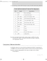
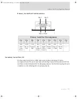
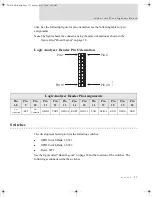
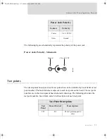
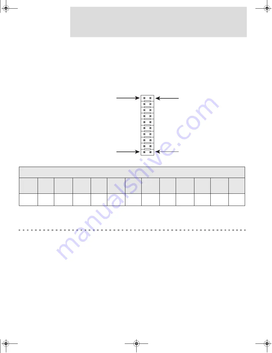
only. See the following figure for pin orientation; see the following table for pin
assignments.
Note
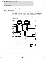
The figure shows the connector using the same orientation as shown in the
figure titled "Board Layout" on page 18.
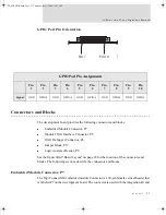
Logic Analyzer Header Pin Orientation
Switches
The development board provides the following switches:
GPIO Switch Bank 1, SW1
GPIO Switch Bank 2, SW2
Reset, SW3
See the figure titled "Board Layout" on page 18 for the location of the switches. The
following sections describe the switches.
Pin 2
Pin 20
Pin 1
Pin 19
00000013
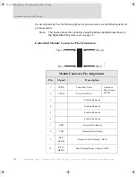
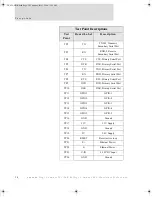
Logic Analyzer Header Pin Assignments
Pin
1-8
Pin
9
Pin
10
Pin
11
Pin
12
Pin
13
Pin
14
Pin
15
Pin
16
Pin
17
Pin
18
Pin
19
Pin
20
Not
Connected
/RST
Not
Connected
GPIO-5
TXD2
GPIO-4
RXD2
GPIO-3
TXD
GPIO-2
RXD
GPIO-1
GND
DC_ME-HWR.book Page 27 Thursday, July 1, 2004 11:12 AM
Содержание Digi Conntect ME
Страница 1: ...TM TM 90000631_A DC_ME HWR book Page 1 Thursday July 1 2004 11 12 AM...
Страница 2: ...DC_ME HWR book Page 2 Thursday July 1 2004 11 12 AM...
Страница 4: ...DC_ME HWR book Page 4 Thursday July 1 2004 11 12 AM...
Страница 47: ...47 M o d u l e S p e c i f i c a t i o n s Bottom DC_ME HWR book Page 47 Thursday July 1 2004 11 12 AM...
Страница 63: ...DC_ME HWR book Page 63 Thursday July 1 2004 11 12 AM...
Страница 64: ...DC_ME HWR book Page 64 Thursday July 1 2004 11 12 AM...


