11
Thermal imager and DMM Operation
Thermal imager basics
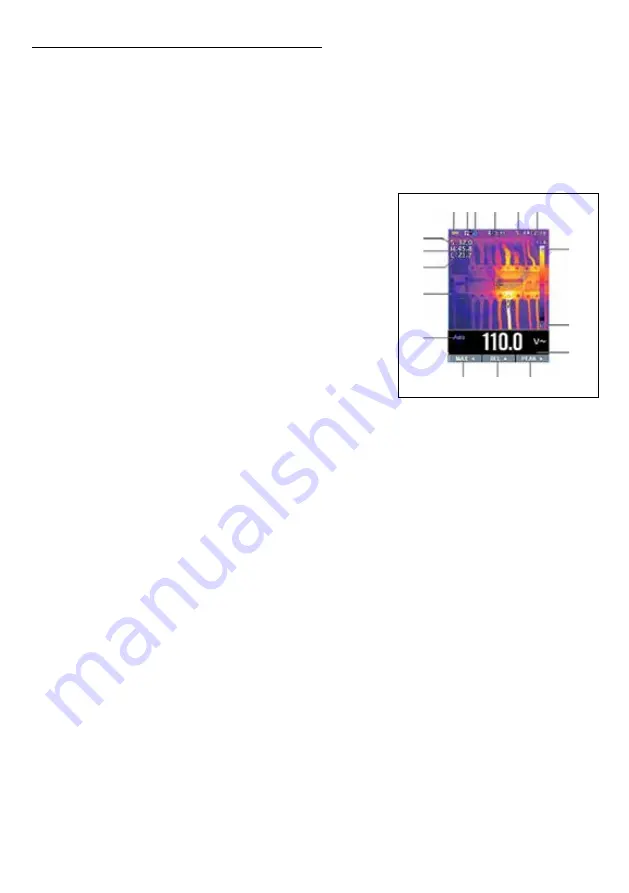
In the Thermal imaging and DMM mode user can measure a targeted surface’s temperature
and use Multimeter at the same time. The measured result will display under the thermal
image.
• Press the red
“IR”
button to open the Thermal Imager. In the image shown the thermal
image is set to color palette
IRON
. Select other palettes in the Menu Settings.
• Open the protective lens cover on the back of the meter.
1. Battery capacity indicator.
2. SD card icon. If this icon is displayed there is an
SD card inserted.
3. Bluetooth icon. If this icon is displayed the Bluetooth
is opened.
4. The currently selected emissivity value. Use the
Thermal Settings Menu to change the emissivity value.
5. Temperature unit icon. Use the Thermal Settings Menu
to select °C, °F, or K.
6. Current time display.
7. Center cross of the thermal imager temperature
measurement represents the center spot temperature
of the scene.
8. Highest temperature spot of the thermal imager temperature measurement, represents
the highest spot temperature of the scene.
9. Minimum temperature spot of the thermal imager temperature measurement, represents
the minimum spot temperature of the scene.
10. Current scene on the thermal image frame.
11. Range icon of the meter.
12. Max soft button.
13. REL soft button.
14. PEAK soft button.
15. DMM measurement, shown below thermal image.
16. Unit of the meter.
17. Lowest reading measured in the current frame.
18. Thermal scale shows the range color for thermal images. The lighter the color, the
warmer the temperature; the darker the color, the cooler the temperature.
19. Highest reading measured in the current frame.
Using the thermal imager
For basic operation follow these steps:
1. Set the function switch to any position.
2. Press the “
IR
” button to switch the thermal imager ON. Target the object by the thermal
imager lens.
1 2 3 4 5 6
12 13 14
7
8
9
10
11
19
18
17
16
15


