OPERATOR’S MANUAL
Control Point
®
11001-1489-201702 Rev B
TROUBLESHOOTING / 89
within the cable assembly or a corroded pin in the connector. If
voltages are present, repair/replace the flowmeter sensor.
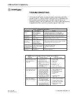
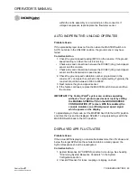
AUTO INOPERATIVE; UNLOAD OPERATES
Probable Cause
If the spreader/sprayer does not function when the MASTER Switch is in
AUTO but does in the UNLOAD position, the ground sensor may have
failed.
Corrective Action
1. Check the ground speed reading (MPH) on the console. If the ground
speed reading is 0 when the truck is moving;
• Check wires and connections between the DICKEY-john ground speed
sensor and the console.
• Check wires and connections between the DICKEY-john ground speed
sensor and the transmission speed sensor.
2. Check the ground speed calibration number programmed in the
console (F7). Compare the number to the original setting. Typically, the
constant should be between 35000 to 60000.
3. Next, replace the ground speed sensor.
4. If the failure continues, replace the MASTER switch module and then
the console.
IMPORTANT: The Control Point
®
system can continue operating
without a “true” ground speed sensor input by setting
the MANUAL SPEED to YES in the GROUND SPEED
CONFIGURATION (F7) screen. With this enabled, the
console simulates an artificial ground speed signal
which appears on the display.
To spread/spray in this mode, set the MASTER Switch to the AUTO position
and drive the truck at the displayed SPEED. To stop spreading, switch the
MASTER Switch back to the OFF position.
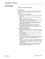
DISPLAYED APR FLUCTUATES
Probable Cause
If the actual APR displaying on console fluctuates more than 5% above and
below the target APR while the vehicle maintains a steady speed, the
System Response should be investigated.
Corrective Action
1. System Response (SYS RSPNS) constant is too large. See heading
"Fine-tuning System Response Constants" in the System
Configuration section.
2. Check APR sensor for loose coupling or slipping on shaft.
Содержание Control Point
Страница 1: ...CONTROL POINT CONTROL SYSTEM Operator s Manual SINCE 1966 ...
Страница 5: ...OPERATOR S MANUAL Control Point 11001 1489 201702 Rev B IV ...
Страница 7: ...OPERATOR S MANUAL Control Point 11001 1489 201702 Rev B 2 SAFETY NOTICES ...
Страница 13: ...OPERATOR S MANUAL Control Point 11001 1489 201702 Rev B 8 INTRODUCTION ...
Страница 29: ...OPERATOR S MANUAL Control Point 11001 1489 201702 Rev B 24 START UP AND FAMILIARIZATION ...
Страница 77: ...OPERATOR S MANUAL Control Point 11001 1489 201702 Rev B 72 KEYBOARD PROGRAMMING ...
Страница 79: ...OPERATOR S MANUAL Control Point 11001 1489 201702 Rev B 74 SYSTEM CALIBRATION ...
Страница 91: ...OPERATOR S MANUAL Control Point 11001 1489 201702 Rev B 86 SYSTEM CALIBRATION ...

