Document No: 9100-127-1958-99 Rev F
1501 Route 34 South, Farmingdale, NJ 07727 Tel: (732)
919-3119 Fax: (732) 751-5778 www.dialight.com
D1xW-C14-409-CTR:
Страница 1: ...ut by a qualified electrician Only genuine Dialight replacement parts must be used when unforeseen repairs are required Observe the national safety rules and regulations during installation Earth Grou...
Страница 2: ...ons Installing the RS485 to additional power supplies Controller layouts Navigating the LCD Display o LCD startup display screens o Setup Screens Configuration o Main Menu Screens o Manual Lighting in...
Страница 3: ...that are covered in the manual D1RW C13 009 CTR consists of D1RW FH009 Flash Head D1RW CTR009 Controller Supply Gen5 dual red white with AC input 48volt sidelights and 8 conductor flash head cable re...
Страница 4: ...ted to Description Color Code Conductor 1 Label A Communications A Grey Conductor 2 Common Common for RS485 Yellow Conductor 3 Label B Communications B Blue Drain wire Ground stud Ground Bare wire Foi...
Страница 5: ...ns need to be added between the RS485 surge board and the translator boards in each of the additional power supplies NOTE For systems larger than E2 daisy chaining between the translator boards is req...
Страница 6: ...3119 Fax 732 751 5778 www dialight com D1xW C13 x09 CTR Controller Requirements NOTE See electrical parameters for power consumption Attach output of Photocell to side light monitor board Marker board...
Страница 7: ...32 919 3119 Fax 732 751 5778 www dialight com D1RWC17409CTR Controller Requirements NOTE See electrical parameters for power consumption Attach output of Photocell to monitor board Marker board J4 Con...
Страница 8: ...te manager and Installer should take a note of this screen including the REV number and the Build number if any future troubleshooting is required x s indicate revision levels and will appear as numbe...
Страница 9: ...will be addressed later in the configuration menu CONFIG TYPE X Enter to change B Use the UP and DWN buttons to scroll and select tower style A D or E Then press ENTR NOTE If Tower Style D is selecte...
Страница 10: ...to P1 Tier 1 0 through 4 can be selected then press ENTR NOTE Repeat for ports 2 through 4 NOTE Each port represents one tier NUM 810 P1 T1 0 u d chg enter done F Select the number of beacons 864 5 s...
Страница 11: ...ashing as indicated in step H Selections available are 20 30 and 40 Use UP and DWN buttons to change and them press ENTR NOTE Factory default is 30fpm NOTE This is a global change that will affect all...
Страница 12: ...cting NO After 18 hours of not transitioning the system will log an event in the log but the system will continue to operate normally based on light conditions No alarm via dry contact or mod bus will...
Страница 13: ...gurations as applicable by pressing the ENTR button to enter into each main menu screen Pressing the CLR in the selected screens takes the user back to the main screens Upon resetting or powering and...
Страница 14: ...ENTR button current and previous alarms the system has encountered are able to be viewed starting with the most current alarm Alarms can be scrolled through using the UP and DWN buttons Each alarm oc...
Страница 15: ...n user input to complete the necessary checks Manual LI TEST enter to Test Status Screen Event Log This screen allows the user access to the Event Log By pressing the ENTR button current and previous...
Страница 16: ...necessary checks NOTE A lighting inspection can be done remotely but the Auto lighting inspection is required The auto does not require covering of the photocell or pressing the selected mode during t...
Страница 17: ...uctures Manual LI TEST IN PROCESS RED OR Manual LI TEST IN PROCESS NWHT Once the test is complete one of the 2 displays will be shown OR Manual LI TEST LIT DONE System will return to configuration scr...
Страница 18: ...LR 8 1 865 W25 BACT 8 1 865 W25 BACT 9 1 865 W25 1 CLR 9 1 865 W25 1 CLR 10 1 865 W25 2 CLR 10 1 865 W25 2 CLR 11 L810 CAL error ACT 11 PCE LOST ACT 12 L810 CAL error CLR 12 SDLT Comm ACT 13 1 ALL L81...
Страница 19: ...C 25 LED ALL 810 OFF Photocell EXT SYNC Heartbeat Failure Failure Failure Failure Failure Day Night Failure Flashes RED RED RED RED RED AMBER GREEN Relay Board Alarm Dry Contact LED s STATUS LED dry c...
Страница 20: ...measured for open or closed with power applied to the base controller NOTE If only one dry contact reader is present then the relays need to be multiplexed together to give one output as shown below...
Страница 21: ...ode E1 system 75W 48Vdc 40 60Vdc Red night mode E1 system 45W 48Vdc 40 60Vdc Red IR night mode E1 system 50W 48Vdc 40 60Vdc White night mode E1 system 30W L810 Obstruction Side Marker Electrical Param...
Страница 22: ...the full warm up and the initial 15 flash countdown menu It will re establish RS485 communications with other power supplies connected to the main controller Ext Sync Input Optional Factory supplied...
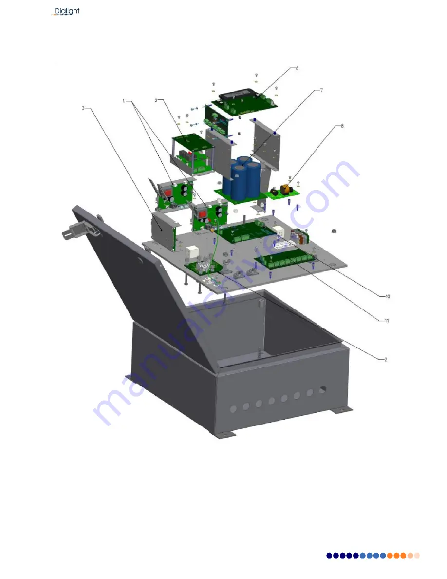
Страница 23: ...Document No 9100 127 1958 99 Rev F 1501 Route 34 South Farmingdale NJ 07727 Tel 732 919 3119 Fax 732 751 5778 www dialight com Replacement Part Numbers D1xW C13 409 CTR...
Страница 24: ...Document No 9100 127 1958 99 Rev F 1501 Route 34 South Farmingdale NJ 07727 Tel 732 919 3119 Fax 732 751 5778 www dialight com D1RW C13 009 CTR...
Страница 25: ...Document No 9100 127 1958 99 Rev F 1501 Route 34 South Farmingdale NJ 07727 Tel 732 919 3119 Fax 732 751 5778 www dialight com D1xW C14 409 CTR...
Страница 26: ...Document No 9100 127 1958 99 Rev F 1501 Route 34 South Farmingdale NJ 07727 Tel 732 919 3119 Fax 732 751 5778 www dialight com D1RW C14 009 CTR...
Страница 27: ...o 9100 127 1958 99 Rev F 1501 Route 34 South Farmingdale NJ 07727 Tel 732 919 3119 Fax 732 751 5778 www dialight com A WARNING Unit should not be lifted from the tabs Dome should not be removed nor ma...
Страница 28: ...cement Red Driver Dual D1RW0084RA Dual IR D1CW0084RA 3A Replacement Red Driver for 48Vdc input Dual D1RW0084RADC Dual IR D1CW0084RADC 4 Replacement White Driver D1RW0084WA 4A Replacement White Driver...
Страница 29: ...s a menu Number Error Active or Cleared Highest was last Status Error Act or Clr displayed NOTE The above are separate screens shown on the LCD both logs are individually accessible Alarm List Error S...
Страница 30: ...to Day There was an issue with the transition from Night Mode to Day Mode The system is in night mode for more than 18 hours Alarm 5 event if PEC trans is configured to NO Side Markers out ALL 810 All...
Страница 31: ...settings to match Tower Alarm 1 AC OFF BAT BAKUP With the Battery connected to the main controller and AC power is down on the system With the Battery connected to the main controller and power down t...