43
2
Hardware Installation
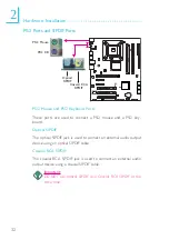
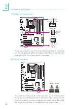
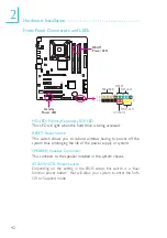
PWR-LED: Power/Standby LED
When the system’s power is on, this LED will light. When the system
is in the S1 (POS - Power On Suspend) or S3 (STR - Suspend To
RAM) state, it will blink every second.
Note:
If a system did not boot-up and the Power/Standby LED did
not light after it was powered-on, it may indicate that the CPU
or memor y module was not installed properly. Please make
sure they are properly inserted into their corresponding socket.
Pin
3
5
1 4
1 6
8
1 0
1 8
2 0
7
9
1 3
1 5
1 7
1 9
2
4
6
HD-LED
(Primary/Secondary IDE LED)
Reserved
ATX-SW
(ATX power switch)
Reserved
RESET
(Reset switch)
SPEAKER
(Speaker connector)
PWR-LED
(Power/Standby LED)
Pin Assignment
HDD LED Power
HDD
N. C.
N. C.
PWRBT+
PWRBT-
N. C.
N. C.
Ground
H/W Reset
Speaker Data
N. C.
Ground
Speaker Power
LED Power (+)
LED Power (+)
LED Power (-) or Standby Signal
DRAM Power LED
This LED will light when the system’s power is on.
Standby Power LED
This LED will light when the system is in the standby mode.
Содержание LanParty DK P35 series
Страница 1: ...System Board User s Manual ...
Страница 110: ...110 4 Supported Software 7 Click Finish ...

