background image

www.dfi.com

1

DFI reserves the right to change the specifications at any time prior to the product's release. This QIG may 

be based on editions that do not resemble your actual products. For the latest revision and more details of 

the installation procedure, please refer to go.dfi.com/KS101-BT or scan the QR code on the right. 

Quick Installation Guide

KS101-BT

• KS101-BT Touch Panel PC

• One sheet of poron foam

• One HDD drive bay kit

Package Contents

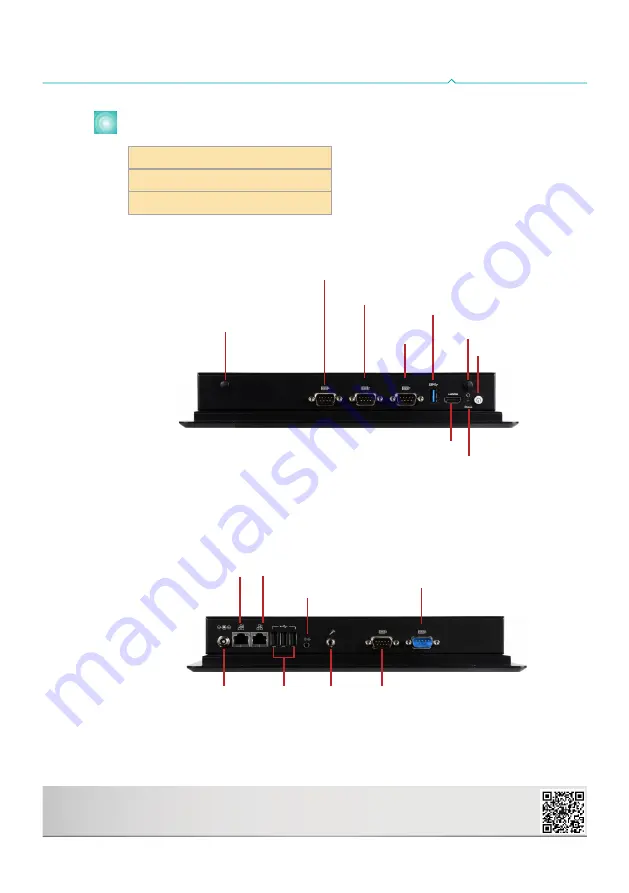
Top View

HDMI

USB 3.0

Antenna

hole

COM 2

(RS232/RS422/RS485)

COM 4/ 8-bit DIO 

Antenna

hole

Reset/

Status LED

Power button

COM 1

(RS232/RS422/RS485)

Bottom View

Line-out

COM 3

(RS232/RS422/RS485)

USB 2.0

LAN 2

DC-in

COM 5

(RS232)

Mic-in

LAN 1

Содержание KS101-BT

Страница 1: ...llation procedure please refer to go dfi com KS101 BT or scan the QR code on the right Quick Installation Guide KS101 BT KS101 BT Touch Panel PC One sheet of poron foam One HDD drive bay kit Package Contents Top View HDMI USB 3 0 Antenna hole COM 2 RS232 RS422 RS485 COM 4 8 bit DIO Antenna hole Reset Status LED Power button COM 1 RS232 RS422 RS485 Bottom View Line out COM 3 RS232 RS422 RS485 USB 2...

Страница 2: ...for later use Mounting screw Mounting screw Mounting screw Installing a SATA Drive The system can accommodate one 2 5 SATA drive 1 Align the mounting holes of the SATA HDD with the mounting holes on the HDD drive bay and use the provided mounting screws to attach the SATA HDD to the drive bay Mounting screw 2 Connect the SATA cable Align the mounting holes of the HDD drive bay with the mounting ho...

Страница 3: ...e slots two full size and one half size slots Here we will demonstrate the installation of a full size Mini PCIe card working in conjunction with a SIM card for 4G connectivity 1 Grasp the Mini PCIe card by its edges and align the notch in the connector of the PCIe card with the notch in the connector on the system board 2 Push the Mini PCIe card down and use the provided mounting screws to secure...

Страница 4: ...Select JP25 Dimming Mode Select JP18 Digital I O 4 7 Output State 1 COM 3 RS232 RS422 RS485 4 1 JP2 JP2 LCD Inverter Power Select SATA 1 4 1 SATA Power 1 SATA 2 0 I C Line out DC in USB 2 USB 2 USB 2 USB 2 USB Power Select 0 JP5 1 2 JP6 5 7 JP7 5V_standby default 1 2 On 5V 2 3 On Clear CMOS Data JP24 Normal default 1 2 On Clear CMOS Data 2 3 On Panel Power Select JP23 12V 1 2 On 5V 3 4 On 3 3V def...

Отзывы: