background image

3

Quick Installation Guide | 

Installing a Mini PCIe Card

Note

:

The system also has one additional full-size Mini PCIe and one half-size Mini PCIe slot that 

use the mSATA and LPC interface respectively. 

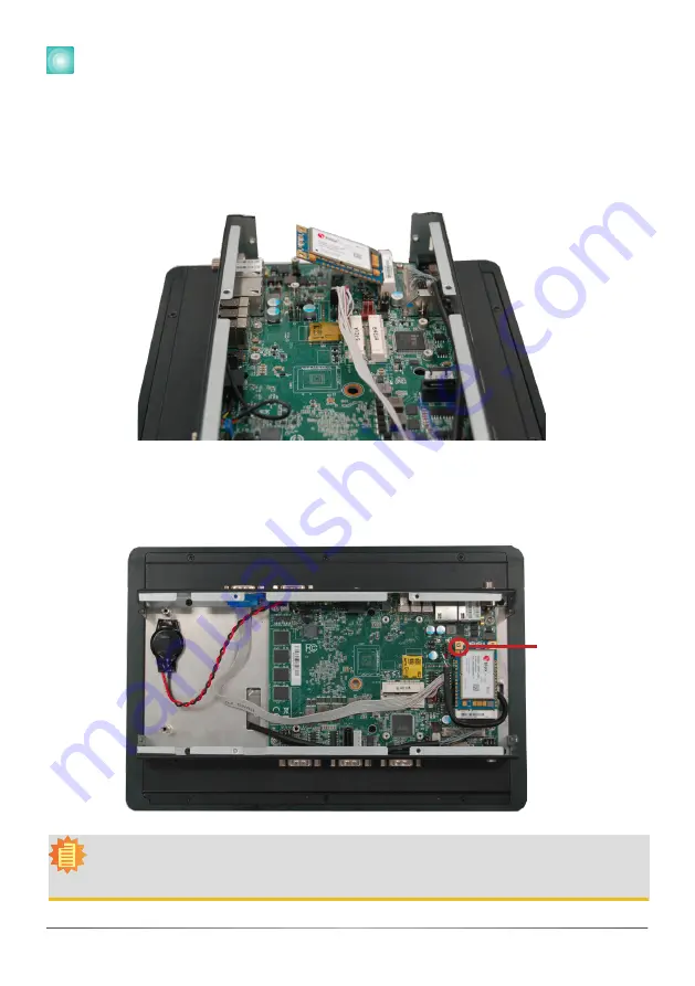
The system board is equipped with 3 Mini PCIe slots: two full-size and one half-size slots. Here we will 

demonstrate the installation of a full-size Mini PCIe card (working in conjunction with a SIM card) for 

4G connectivity. 

1.  Grasp the Mini PCIe card by its edges and align the notch in the connector of the PCIe card with 

the notch in the connector on the system board.

2.  Push the Mini PCIe card down and use the provided mounting screws to secure the card on the 

system board.

Mounting screw

Содержание KS101-BT

Страница 1: ...llation procedure please refer to go dfi com KS101 BT or scan the QR code on the right Quick Installation Guide KS101 BT KS101 BT Touch Panel PC One sheet of poron foam One HDD drive bay kit Package Contents Top View HDMI USB 3 0 Antenna hole COM 2 RS232 RS422 RS485 COM 4 8 bit DIO Antenna hole Reset Status LED Power button COM 1 RS232 RS422 RS485 Bottom View Line out COM 3 RS232 RS422 RS485 USB 2...

Страница 2: ...for later use Mounting screw Mounting screw Mounting screw Installing a SATA Drive The system can accommodate one 2 5 SATA drive 1 Align the mounting holes of the SATA HDD with the mounting holes on the HDD drive bay and use the provided mounting screws to attach the SATA HDD to the drive bay Mounting screw 2 Connect the SATA cable Align the mounting holes of the HDD drive bay with the mounting ho...

Страница 3: ...e slots two full size and one half size slots Here we will demonstrate the installation of a full size Mini PCIe card working in conjunction with a SIM card for 4G connectivity 1 Grasp the Mini PCIe card by its edges and align the notch in the connector of the PCIe card with the notch in the connector on the system board 2 Push the Mini PCIe card down and use the provided mounting screws to secure...

Страница 4: ...Select JP25 Dimming Mode Select JP18 Digital I O 4 7 Output State 1 COM 3 RS232 RS422 RS485 4 1 JP2 JP2 LCD Inverter Power Select SATA 1 4 1 SATA Power 1 SATA 2 0 I C Line out DC in USB 2 USB 2 USB 2 USB 2 USB Power Select 0 JP5 1 2 JP6 5 7 JP7 5V_standby default 1 2 On 5V 2 3 On Clear CMOS Data JP24 Normal default 1 2 On Clear CMOS Data 2 3 On Panel Power Select JP23 12V 1 2 On 5V 3 4 On 3 3V def...

Отзывы: