www.d
fi
.com
Chapter 2 Hardware Installation
9
Chapter 2
1
ON
2 3 4
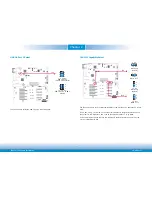
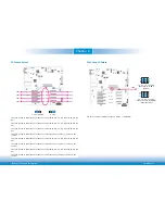
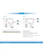
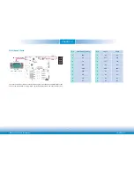
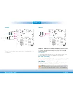
10G PHY Capability Select
JP9
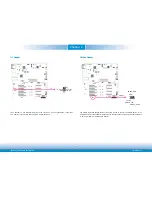
The JP19 and JP9 are used to select the capability of 10G PHY lanes 0,1 and lanes 2,3 respec-
tively.
If 10G_PHY_CAP_0,1 is tied low on the Carrier, this indicates to the Module that the PHY on
the Carrier for 10G interfaces 0 and 1 can be configured by either I
2
C or by MDIO.
If the Carrier leaves the line NC, then this indicates to the Module that the Carrier PHY can
only be configured by MDIO.
1
3
2
1
3
2
JP19
2-3 On:
MDIO or I
2
C
1-2 On:
MDIO only
(default)
3
1 2
3
1 2
1-2 On:
MDIO only
(default)
2-3 On:
MDIO or I
2
C
1
ON
2 3 4
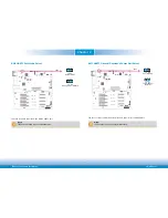
USB 2.0 Port 3 Select
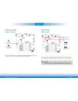
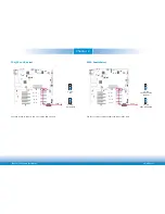
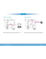
The JP4 is used to select the USB 2.0 port 3 connection path.
JP4
1-3, 2-4 On:
USB 2.0 Port 3
to Rear I/O Connector
5
1
3
2
4
6
3-5, 4-6 On:
USB 2.0 Port 3 to BMC
(default)
5
1
3
2
4
6


