


www.d
fi
.com
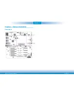
Chapter 2 Hardware Installation
13
Chapter 2
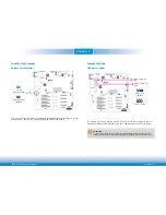
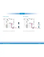
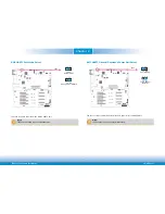
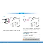
VCC5_IN Power Select
1
ON
2 3 4
JP26
The JP26 is used to select the power rail for module VCC5_IN pins when in ATX or AT mode.
1-2 On:
+5V_standby (default)
3-4 On: +5V
5-6 On: NC
5
1
3
2
4
6
5
2
4
6
1
3
5
2
4
6
1
3
ATX/AT Mode Select (Power_OK)
1
ON
2 3 4
JP27
The JP27 allows you to select the PWR_OK connection state when setting power at ATX or AT
mode.
1
3
2
1
3
2
1-2 On:
PWR_OK from ATX PS PWR_OK
(default)
2-3 On:
PWR_OK from BMC GPO
1
3
2
1-X:
No PWR_OK when in AT Mode
Note:
JP27 and JP28 need to be set simultaneously. Please refer next page for JP28 descrip-
tion.


