background image

38

2

Hardware Installation

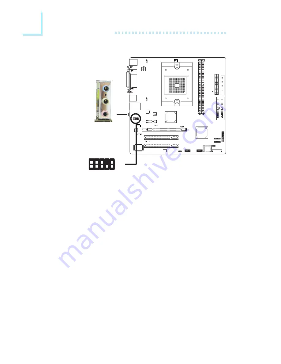
Audio

W

W

Rear audio

Front audio

Line-out

Line-in

Mic-in

1

Mic

Mic P

o

w

e

r

AuD_R_Out

N.

 C

.

AuD_L_Out

GND

AuD_Vcc

Key

2

1 0

AuD_R_Return

AuD_L_Return

9

Rear Panel Audio (CN6)

Line-in (Light Blue)

In a 2-channel mode, this jack is used to connect any audio
devices such as Hi-fi set, CD player, tape player, AM/FM radio
tuner, synthesizer, etc. In a 4-channel or 6-channel mode, this jack
functions as rear right/left speaker out.

Line-out (Lime)

In a 2-channel mode, this jack is used to connect a headphone
or external speakers. In a 4-channel or 6-channel mode, this jack
functions as front right/left speaker out.

Mic-in (Pink)

In a 2-channel or 4-channel mode, this jack is used to connect an
external microphone. In a 6-channel mode, this jack functions as
Center/Subwoofer.

Содержание C51G-ML

Страница 1: ...91100605 C51G ML System Board User s Manual ...

Страница 2: ...r any particular purpose The user will assume the entire risk of the use or the results of the use of this document Further the manufacturer reserves the right to revise this publication and make changes to its contents at any time without obligation to notify any person or entity of such revisions or changes 2006 All Rights Reserved Trademarks Windows 98 Windows 98 SE Windows ME Windows 2000 Wind...

Страница 3: ...rticular installation If this equipment does cause harmful interference to radio or television reception which can be determined by turning the equipment off and on the user is encouraged to try to correct the interference by one or more of the following measures Reorient or relocate the receiving antenna Increase the separation between the equipment and the receiver Connect the equipment into an ...

Страница 4: ...ard Chapter 2 Hardware Installation System Board Layout System Memory CPU Jumper Settings Rear Panel I O Ports I O Connectors Chapter 3 BIOS Setup Award BIOS Setup Utility NVRAID BIOS Updating the BIOS Chapter 4 Supported Softwares Chapter 5 Cool n Quiet Technology Chapter 6 RAID Appendix A System Error Message Appendix B Troubleshooting 5 5 6 6 7 7 8 8 10 16 16 17 19 25 30 40 55 55 99 100 102 115...

Страница 5: ...orized replacement or alteration of components and product specifications 2 The warranty is void if the product has been subjected to physical abuse improper installation modification accidents or unauthorized repair of the product 3 Unless otherwise instructed in this user s manual the user may not under any circumstances attempt to perform service adjustments or repairs on the product whether in...

Страница 6: ...tant Electrostatic discharge ESD can damage your processor disk drive and other components Perform the upgrade instruction procedures described at an ESD workstation only If such a station is not available you can provide some ESD protection by wearing an antistatic wrist strap and attaching it to a metal part of the system chassis If a wrist strap is unavailable establish and maintain contact wit...

Страница 7: ...r to the information listed above This may differ in accordance to the sales region or models in which it was sold For more information about the standard package in your region please contact your dealer or sales representative Before Using the System Board Before using the system board prepare basic system components If you are installing the system board in a new system you will need at least t...

Страница 8: ...evices 1 PCI Express x16 slot 1 PCI Express x1 slot 2 PCI slots Award BIOS 4Mbit flash memory ACPI and OS Directed Power Management ACPI STR Suspend to RAM function Wake On PS 2 Keyboard Mouse Wake On USB Keyboard Mouse Wake On LAN Wake On Ring RTC timer to power on the system AC power failure recovery Monitors CPU system temperature Monitors 5V 12V 3 3V 5VSB Vbat Vcore Vdimm Vchip voltages Monito...

Страница 9: ...ouse port 1 mini DIN 6 PS 2 keyboard port 1 parallel port 1 COM port 1 VGA port 1 RJ45 LAN port 4 USB 2 0 1 1 ports Line in line out and mic in jacks 2 connectors for 4 additional external USB 2 0 1 1 ports 1 front audio connector for external line out and mic in jacks 1 CD in internal audio connector 1 coaxial S PDIF connector 1 IrDA connector 2 Serial ATA connectors 2 IDE connectors 1 floppy con...

Страница 10: ...DRAM Timing and Config section of the BIOS The AMD Cool n QuietTM technology allows the system to detect the CPU s tasks and utilization status When the CPU s task slows down the system effec tively lowers power consumption by lowering its CPU speed and voltage subsequently decreasing its noise level PCI Express is a high bandwidth I O infrastructure that possesses the ability to scale speeds by f...

Страница 11: ...g system boot up Once the CPU s temperature exceeded the tempera ture limit pre defined by the CPU the system will automatically shut down This preventive measure has been added to protect the CPU from damage and insure a safe computing environment Double Data Rate SDRAM DDR SDRAM is a type of SDRAM that doubles the data rate through reading and writing at both the rising and falling edge of each ...

Страница 12: ... devices like CD recorders Serial ATA is a storage interface that is compli ant with SATA 1 0 specification nForceTM 410 MCP Media and Communications Processor supports Serial ATA speed of up to 3Gb s Serial ATA improves hard drive performance faster than the standard parallel ATA whose data transfer rate is 100MB s nForceTM 410 MCP allows configuring RAID on the Serial ATA drives It supports RAID...

Страница 13: ...ment Event signal to remotely wake up the PC Important If you are using a modem add in card the 5VSB power source of your power supply must support a minimum of 720mA This feature allows the network to remotely wake up a Soft Power Down Soft Off PC It is supported via the onboard LAN port or via a PCI LAN card that uses the PCI PME Power Management Event signal However if your system is in the Sus...

Страница 14: ... Plug and Play with operating systems that support OS Direct Power Management Currently only Windows 2000 XP supports the ACPI function ACPI when enabled in the Power Management Setup will allow you to use the Suspend to RAM function With the Suspend to RAM function enabled you can power off the system at once by pressing the power button or selecting Standby when you shut down Windows 2000 XP wit...

Страница 15: ...failure recovery When power returns after an AC power fail ure you may choose to either power on the system manually let the system power on au tomatically or return to the state where you left off before power failure occurs ...

Страница 16: ...16 2 Hardware Installation System Board Layout Chapter 2 Hardware Installation ...

Страница 17: ... is not available you can provide some ESD protection by wearing an antistatic wrist strap and attaching it to a metal part of the system chassis If a wrist strap is unavailable establish and maintain contact with the system chassis throughout any procedures requiring ESD protection The system board supports DDR SDRAM DIMM Double Data Rate SDRAM DDR SDRAM is a type of SDRAM that doubles the data r...

Страница 18: ...a DIMM socket on the system board Pin 1 of the DIM module must correspond with Pin 1 of the socket 1 Pull the tabs which are at the ends of the socket to the side 2 Position the DIMM above the socket with the notch in the module aligned with the key on the socket 3 Seat the module vertically into the socket Make sure it is completely seated The tabs will hold the DIMM in place Pin 1 Notch Key Tab ...

Страница 19: ...unt 754 pin CPU socket This socket is exclusively designed for installing an AMD CPU Installing the CPU 1 Make sure the PC and all other peripheral devices connected to it has been powered down 2 Disconnect all power cords and cables 3 Locate the 754 pin CPU socket on the system board X ...

Страница 20: ...ocket refer to the en larged view shown below Important Handle the CPU by its edges and avoid touching the pins 4 Unlock the socket by pushing the lever sideways away from the socket then lifting it up to a 90o angle Make sure the lever is lifted to at least this angle otherwise the CPU will not fit in properly Lever Gold mark ...

Страница 21: ... easily be inserted without exerting any force Important Do not force the CPU into the socket Forcing the CPU into the socket may bend the pins and damage the CPU 7 Once the CPU is in place push down the lever to lock the socket The lever should click on the side tab to indicate that the CPU is completely secured in the socket Side tab ...

Страница 22: ...e differs from the one in this section please follow the installation guide in the package 1 Before you install the fan heat sink you must apply a thermal paste onto the top of the CPU The thermal paste is usually supplied when you purchase the CPU or fan heat sink assembly Do not spread the paste all over the surface When you later place the heat sink on top of the CPU the compound will dis perse...

Страница 23: ... Now hook one side of the retention clip onto the retention module base by fitting the holes on the retention clip into the retaining tabs of the retention module base Retention clip Retention module base Retaining tabs Retaining tabs Side View Top View Retaining tab ...

Страница 24: ...le to secure the fan and heat sink as sembly in place if it did not fit properly onto the retention module base Retention lever 6 Connect the CPU fan s cable connector to the CPU fan connec tor on the system board 5 Move the retention lever to its opposite side then push it down to lock the fan and heat sink assembly to the retention module base Note Make sure there is sufficient air circulation a...

Страница 25: ...ored in the ROM BIOS To load the default values stored in the ROM BIOS please follow the steps below 1 Power off the system and unplug the power cord 2 Set JP1 pins 2 and 3 to On Wait for a few seconds and set JP1 back to its default setting pins 1 and 2 On 3 Now plug the power cord and power on the system If your reason for clearing the CMOS data is due to incorrect setting of the processor s rat...

Страница 26: ...Setting submenu and press Enter 6 Set the processor s clock ratio to its default setting or an appro priate bus clock or ratio Refer to the Genie BIOS Setting section in chapter 3 for more information 7 Press Esc to return to the main menu of the BIOS setup utility Select Save Exit Setup and press Enter 8 Type Y and press Enter ...

Страница 27: ...use port Selecting 5VSB will allow you to use the PS 2 keyboard or PS 2 mouse to wake up the system BIOS Setting Configure the PS 2 keyboard mouse wake up function in the Power Management Setup submenu of the BIOS Refer to chapter 3 for more information Important The 5VSB power source of your power supply must support 720mA 1 3 2 1 3 2 ...

Страница 28: ...he power of the USB ports Selecting 5VSB will allow you to use the USB keyboard or USB mouse to wake up the system Important If you are using the Wake On USB Keyboard Mouse function for 2 USB ports the 5VSB power source of your power supply must support 1 5A For 3 or more USB ports the 5VSB power source of your power supply must support 2A 1 3 2 1 3 2 1 3 2 1 3 2 ...

Страница 29: ... can detect most PCI Express cards However if you are using cards such as Gigabyte GC LC05 BroadCom BCM5721 or other cards not detected by the system set JP2 and or JP5 to 2 3 On Configuring the jumper to 2 3 On will allow the system to detect the PCI Express card JP2 is used to configure the PCI Express card installed in the PCIE2 slot JP5 is used to configure the PCI Express card installed in th...

Страница 30: ...ear panel I O ports consist of the following PS 2 mouse port PS 2 keyboard port Parallel port COM port VGA port USB ports LAN port Line in port Line out port Mic in port PS 2 Mouse Parallel COM VGA PS 2 K B LAN USB 1 USB 3 4 Line in Line out Mic in USB 2 ...

Страница 31: ...ur computer prior to connecting or disconnecting a mouse or keyboard Failure to do so may damage the system board Wake On PS 2 Keyboard Mouse The Wake On PS 2 Keyboard Mouse function allows you to use the PS 2 keyboard or PS 2 mouse to power on the system To use this function Jumper Setting JP7 must be set to 2 3 On 5VSB Refer to PS 2 Power Select in this chapter for more information BIOS Setting ...

Страница 32: ...rated Peripherals submenu Super IO Device section of the BIOS Refer to chapter 3 for more information Setting SPP Standard Parallel Port ECP Extended Capabilities Port EPP Enhanced Parallel Port Function Allows normal speed operation but in one direction only Allows parallel port to operate in bidirectional mode and at a speed faster than the SPP s data transfer rate Allows bidirectional parallel ...

Страница 33: ...ort is RS 232 asynchronous commu nication port with 16C550A compatible UARTs that can be used with modems serial printers remote display terminals and other se rial devices BIOS Setting Configure the serial ports in the Integrated Peripherals submenu Super IO Device section of the BIOS Refer to chapter 3 for more information COM W ...

Страница 34: ...location CN1 After you plug the monitor s cable connector into the VGA port gently tighten the cable screws to hold the connector in place BIOS Setting Configure the onboard VGA in the Advanced Chipset Features submenu of the BIOS Refer to chapter 3 for more information Driver Installation Install the graphics driver Refer to chapter 4 for more information VGA W ...

Страница 35: ...unted on a card edge bracket Install the card edge bracket to an available slot at the rear of the system chassis then insert the con nector that is attached to the USB port cables to J7 or J8 Make sure pin 1 of the cable connector is aligned with pin 1 of the J7 or J8 BIOS Setting Configure the onboard USB in the Integrated Peripherals submenu Onboard Device section of the BIOS Refer to chapter 3...

Страница 36: ...ouse The Wake On USB Keyboard Mouse function allows you to use a USB keyboard or USB mouse to wake up a system from the S3 STR Suspend To RAM state To use this function Jumper Setting JP3 and or JP4 must be set to 2 3 On 5VSB Refer to USB Power Select in this chapter for more information Important If you are using the Wake On USB Keyboard Mouse function for 2 USB ports the 5VSB power source of you...

Страница 37: ...oard to connect to a local area network by means of a network hub BIOS Setting Configure the onboard LAN in the Integrated Peripherals submenu Onboard Device section of the BIOS Refer to chapter 3 for more information Driver Installation Install NVIDIA Chipset System Drivers Refer to chapter 4 for more information W LAN ...

Страница 38: ... Hi fi set CD player tape player AM FM radio tuner synthesizer etc In a 4 channel or 6 channel mode this jack functions as rear right left speaker out Line out Lime In a 2 channel mode this jack is used to connect a headphone or external speakers In a 4 channel or 6 channel mode this jack functions as front right left speaker out Mic in Pink In a 2 channel or 4 channel mode this jack is used to co...

Страница 39: ...o chapter 4 for more information Front Audio The front audio connector at location J4 allows you to connect to the line out and mic in jacks that are at the front panel of your system Using this connector will disable the rear audio s line out and mic in functions Remove the jumper caps from pins 5 6 and pins 9 10 of J4 prior to connecting the front audio cable connector Make sure pin 1 of the cab...

Страница 40: ... Installation Internal I O Connectors CD in Connector W The CD in connector at location J32 is used to receive audio from a CD ROM drive TV tuner or MPEG card 1 4 Left audio channel Right audio channel Ground Ground ...

Страница 41: ... ports Your S PDIF ports may be mounted on a card edge bracket Install the card edge bracket to an available slot at the rear of the system chassis then connect the audio cable connector to J3 Make sure pin 1 of the audio cable connector is aligned with pin 1 of J3 W 1 5 SPDIF in GND SPDIF out Key 5V ...

Страница 42: ...ng the Floppy Disk Drive Cable Install one end of the floppy disk drive cable into the shrouded floppy disk header J23 on the system board and the other end most connector to the drive you want to designate as Drive A If you are connecting another drive Drive B install the middle connector of the cable to the drive The colored edge of the daisy chained ribbon cable should be aligned with pin 1 of ...

Страница 43: ...al ATA Cables Connect one end of the Serial ATA cable to SATA 1 J17 or SATA 2 J16 and the other end to your Serial ATA device Configuring RAID The system board allows configuring RAID on Serial ATA drives Re fer to chapter 6 for steps in configuring RAID X GND TXP TXN GND RXN RXP GND 1 7 1 7 SATA 2 SATA 1 ...

Страница 44: ...the drives to the system board An IDE ribbon cable have 3 connectors on them one that plugs into an IDE connector on the system board and the other 2 connects to IDE devices The connector at the end of the cable is for the Master drive and the connector in the middle of the cable is for the Slave drive Connecting the IDE Disk Drive Cable Install one end of the IDE cable into the IDE 1 header J1 on...

Страница 45: ... ATA 133 hard drives We recommend that you use hard drives from the same manufacturer In a few cases drives from two different manufacturers will not function properly when used together The problem lies in the hard drives not the system board Important If you encountered problems while using an ATAPI CD ROM drive that is set in Master mode please set the CD ROM drive to Slave mode Some ATAPI CD R...

Страница 46: ... function defined on the system board Make sure to connect the cable connector to the IrDA connector according to their pin functions BIOS Setting Configure IrDA in the Integrated Peripherals submenu Super IO Device section of the BIOS Driver Installation You may need to install the proper drivers in your operating system to use the IrDA function Refer to your operating system s manual or document...

Страница 47: ...ional cooling fans The cooling fans will provide adequate airflow throughout the chassis to prevent overheating the CPU and system board components BIOS Setting The PC Health Status submenu of the BIOS will display the current speed of the cooling fans Refer to chapter 3 for more information X X X CPU fan 3 1 Ground Power Sense Chipset fan 1 3 Ground Power Sense System fan 1 3 Ground Power Sense ...

Страница 48: ...system s power is on Warning When the DRAM Power LED lit red it indicates that power is present on the DDR sockets Power off the PC then unplug the power cord prior to installing any memory modules Failure to do so will cause severe damage to the motherboard and components DRAM Power LED ...

Страница 49: ...nserted onto CN8 Your power supply unit also comes with a 4 pin 12V power connector The 12V power enables the delivery of more 12VDC current to the processor s Voltage Regulator Module VRM Connect the 4 pin power connector to CN9 X 13 1 12 24 3 3VDC 3 3VDC Ground 5VDC Ground 5VDC Ground PWR_OK 5VSB 12VDC 12VDC 3 3VDC 3 3VDC 12VDC Ground PS_ON Ground Ground Ground NC 5VDC 5VDC 5VDC Ground X 1 2 4 3...

Страница 50: ...may exceed the minimum power requirement To ensure that adequate power is provided we strongly recommend that you use a minimum of 400 Watt or greater power supply Important Insufficient power supplied to the system may result in instability or the add in boards and peripherals not functioning properly Calculating the system s approximate power usage is important to ensure that the power supply me...

Страница 51: ...hus prolonging the life of the power supply or system SPEAKER Speaker Connector This connects to the speaker installed in the system chassis ATX SW ATX Power Switch Depending on the setting in the BIOS setup this switch is a dual function power button that will allow your system to enter the Soft Off or Suspend mode Refer to Soft Off By PBTN in the Power Management Setup Chapter 3 X J21 PWR LED AT...

Страница 52: ...n it may indicate that the CPU or memory module was not installed properly Please make sure they are properly inserted into their corresponding socket Pin 3 5 14 16 8 10 18 20 7 9 13 15 17 19 2 4 6 HD LED Primary Secondary IDE LED Reserved ATX SW ATX power switch Reserved RESET Reset switch SPEAKER Speaker connector PWR LED Power Standby LED Pin Assignment HDD LED Power HDD N C N C PWRBT PWRBT N C...

Страница 53: ...slot align the graphics card above the slot then press it down firmly until it is completely seated in the slot The retaining clip of the slot will automatically hold the graphics card in place PCI Express x1 Install PCI Express x1 cards such as network cards or other cards that comply to the PCI Express specifications into the PCI Express x1 slot PCI Express Slots PCI Express x1 PCI Express x16 ...

Страница 54: ... is an auxiliary source of power when the main power is shut off Safety Measures Danger of explosion if battery incorrectly replaced Replace only with the same or equivalent type recommend by the manufacturer Dispose of used batteries according to the battery manufacturer s instructions Battery X ...

Страница 55: ...creen Press DEL to enter setup If the message disappears before you respond restart the system or press the Reset button You may also restart the system by press ing the Ctrl Alt and Del keys simultaneously When you press Del the main menu screen will appear Chapter 3 BIOS Setup Phoenix AwardBIOS CMOS Setup Utility X Genie BIOS Setting Load Fail Safe Defaults Load Optimized Defaults Set Supervisor...

Страница 56: ...ds from 00 to 59 Standard CMOS Features Use the arrow keys to highlight Standard CMOS Features and press Enter A screen similar to the one below will appear Date mm dd yy Time hh mm ss X IDE Channel 0 Master X IDE Channel 0 Slave X IDE Channel 1 Master X IDE Channel 1 Slave X IDE Channel 2 Master X IDE Channel 3 Master Drive A Drive B Halt On Base Memory Extended Memory Total Memory Phoenix AwardB...

Страница 57: ... drives IDE Channel 2 Master and IDE Channel 3 Master will not appear on the following 2 conditions 1 If Serial ATA 1 is set to Disabled 2 If SATA 1 Primary RAID and or SATA 1 Secondary RAID are set to Enabled The fields mentioned in items 1 and 2 are in the Integrated Peripherals submenu OnChip IDE Device section of the BIOS Settings in this section are controlled by the NVIDIA RAID BIOS Used to ...

Страница 58: ...n operating systems require that you select CHS or Large Please check your operating system s manual or Help desk on which one to select The settings on the screen are for reference only Your version may not be identical to this one IDE HDD Auto Detection IDE Channel 0 Master Access Mode Capacity Cylinder Head Precomp Landing Zone Sector Phoenix AwardBIOS CMOS Setup Utility IDE Channel 0 Master It...

Страница 59: ...ming Landing Zone This field displays the number of cylinders specified as the landing zone for the read write heads Sector This field displays the number sectors per track Drive A and Drive B These fields identify the types of floppy disk drives installed None No floppy drive is installed 360K 5 25 in 5 1 4 in standard drive 360KB capacity 1 2M 5 25 in 5 1 4 in AT type high density drive 1 2MB ca...

Страница 60: ...iskette The system boot will not stop for a disk error it will stop for all other errors All But Disk Key The system boot will not stop for a disk or keyboard error it will stop for all other errors Base Memory Displays the amount of base or conventional memory installed in the system The value of the base memory is typically 512K for systems with 512K memory installed on the motherboard or 640K f...

Страница 61: ...rus Warning CPU Internal Cache External Cache Quick Power On Self Test First Boot Device Second Boot Device Third Boot Device Boot Other Device Swap Floppy Drive Boot Up Floppy Seek Boot Up NumLock Status Typematic Rate Setting x Typematic Rate Chars Sec x Typematic Delay Msec Security Option APIC Mode MPS Version Control For OS OS Select For DRAM 64MB HDD S M A R T Capability Full Screen LOGO Sho...

Страница 62: ... to move it down the list The settings on the screen are for reference only Your version may not be identical to this one Phoenix AwardBIOS CMOS Setup Utility Removable Device Priority Item Help Menu Level XX Use or to select a device then press to move it up or to move it down the list Press ESC to exit this menu Move PU PD Change Priority F10 Save ESC Exit F5 Previous Values F6 Fail Safe Default...

Страница 63: ... we recommend that you first disable this field Also disable this field if you are installing or running certain operating sys tems like Windows 95 98 2000 or the operating system may not install nor work Hard Disk Boot Priority This field is used to select the boot sequence of the hard drives Move the cursor to this field then press Enter Use the Up or Down arrow keys to select a device then pres...

Страница 64: ...ystem according to the sequence of the drive selected Set Boot Other Device to Enabled if you wish to boot from another device Swap Floppy Drive When this field is enabled and the system is booting from the floppy drive the system will boot from drive B instead of drive A When this field is disabled and the system is booting from the floppy drive the system will boot from drive A You must have two...

Страница 65: ...lerate cursor movements with the ar row keys You can then select the typematic rate and typematic delay in the Typematic Rate Chars Sec and Typematic Delay Msec fields below Typematic Rate Chars Sec This field allows you to select the rate at which the keys are acceler ated Typematic Delay Msec This field allows you to select the delay between when the key was first depressed and when the accelera...

Страница 66: ...ogy for ATA IDE and SCSI drives The drive will provide suffi cient notice to the system or user to backup data prior to the drive s failure The default is Disabled If you are using hard drives that support S M A R T set this field to Enabled SMART is sup ported in ATA 33 or later hard drives Full Screen Logo Show This field is applicable only if you want a particular logo to appear during system b...

Страница 67: ... Errata 94 Enhancement function The options are Auto and Disabled CPU Spread Spectrum This field is used to enable or disable the CPU spread spectrum The settings on the screen are for reference only Your version may not be identical to this one Phoenix AwardBIOS CMOS Setup Utility Advanced Chipset Features Item Help Menu Level X Move Enter Select F1 General Help PU PD Value F10 Save ESC Exit F5 P...

Страница 68: ...used to select whether to initialize the onboard VGA PCI Express or PCI first when the system boots PCI Slot When the system boots it will first initialize PCI Onboard When the system boots it will first initialize the onboard VGA PCIEx When the system boots it will first initialize the PCI Express x16 graphics card Bottom of 32 bit 31 24 IO This field is used to select the memory that will be rem...

Страница 69: ...e controller is enabled The larger the range of the Cache RAM the higher the efficiency of the system Dual VGA Support This field is used to enable or disable the dual VGA function Frame Buffer Size This field is used to select the total amount of system memory locked by the BIOS for video A larger frame buffer size should result in higher video performance ...

Страница 70: ...rimary Master UDMA Primary Slave UDMA OnChip IDE Channel1 Secondary Master PIO Secondary Slave PIO Secondary Master UDMA Secondary Slave UDMA IDE DMA Transfer Access IDE Prefetch Mode IDE HDD Block Mode On Chip Serial ATA Setting Serial ATA 1 RAID Enable SATA 1 Primary RAID SATA 1 Secondary RAID Phoenix AwardBIOS CMOS Setup Utility OnChip IDE Device Item Help Menu Level XX Move Enter Select F1 Gen...

Страница 71: ...e best available mode after checking your drive Auto The BIOS will automatically set the system according to your hard disk drive s timing Mode 0 4 You can select a mode that matches your hard disk drive s timing Caution Do not use the wrong setting or you will have drive errors Primary Master Slave UDMA and Secondary Master Slave UDMA These fields allow you to set the Ultra DMA in use When Auto i...

Страница 72: ...size will depend on the type of hard disk drive Disabled The IDE HDD uses the standard mode Serial ATA 1 This field is used to enable or disable SATA 1 and SATA 2 RAID Enable This field is used to enable or disable the RAID function of the Serial ATA drives SATA 1 Primary RAID and SATA 1 Secondary RAID These fields are used to enable or disable the RAID function of SATA 1 and SATA 2 ...

Страница 73: ...MAC Media Interface V1 1 V2 0 Shadow Disabled Auto Auto Pin Strap OnChip USB This field is used to enable or disable USB 1 1 and or USB 2 0 USB Memory Type This field is used to select the memory allocated for USB The op tions are Shadow and Base Memory 640K USB Keyboard Support If you are using a USB keyboard device set this field to Enabled AC97 Audio Auto Select this option when using the onboa...

Страница 74: ...dress for the IR device 3F8 IRQ4 2F8 IRQ3 3E8 IRQ4 2E8 IRQ3 Allows you to manually select an I O address for the IR device Disabled Disables the IR device Super IO Device The settings on the screen are for reference only Your version may not be identical to this one Phoenix AwardBIOS CMOS Setup Utility Super IO Device Item Help Menu Level XX Move Enter Select F1 General Help PU PD Value F10 Save E...

Страница 75: ...nboard parallel port Disabled Disables the onboard parallel port Parallel Port Mode The options are SPP EPP ECP and ECP EPP These apply to a standard specification and will depend on the type and speed of your device Refer to your peripheral s manual for the best option SPP Allows normal speed operation but in one direction only ECP Extended Capabilities Port Allows parallel port to operate in bid...

Страница 76: ...e S1 POS Enables the Power On Suspend function S3 STR Enables the Suspend to RAM function The settings on the screen are for reference only Your version may not be identical to this one Phoenix AwardBIOS CMOS Setup Utility Power Management Setup Item Help Menu Level X Move Enter Select F1 General Help PU PD Value F10 Save ESC Exit F5 Previous Values F6 Fail Safe Defaults F7 Optimized Defaults ACPI...

Страница 77: ...his selection will cause the system to turn off the vertical and horizontal synchronization ports and write blanks to the video buffer Blank Screen This option only writes blanks to the video buffer DPMS Initializes display power management signaling Use this option if your video board supports it HDD Power Down This is selectable only when the Power Management field is set to User Define When the...

Страница 78: ...y power off your system Wake Up On LAN Set this field to Enabled to wake up the system via the onboard LAN or via a LAN card that uses the PCI PME Power Manage ment Event signal to remotely wake up the system Access to the LAN card will cause the system to wake up Refer to the card s documentation for more information Resume By Ring When this field is set to Enabled the system will power on to re ...

Страница 79: ...u to use the PS 2 keyboard or PS 2 mouse to power on the system Button only Default setting Uses the power button to power on the system Hot Key Select the function key you would like to use to power on the system in the Hot Key Power On field Mouse Move Move the PS 2 mouse to wake up the system Mouse Click Click the PS 2 mouse to wake up the system Any Key Press any key to power on the system Key...

Страница 80: ...IRQ Resources field The settings on the screen are for reference only Your version may not be identical to this one Phoenix AwardBIOS CMOS Setup Utility PnP PCI Configurations Item Help Menu Level X Move Enter Select F1 General Help PU PD Value F10 Save ESC Exit F5 Previous Values F6 Fail Safe Defaults F7 Optimized Defaults Resources Controlled By x IRQ Resources PCI VGA Palette Snoop PCI Express ...

Страница 81: ...Select F1 General Help PU PD Value F10 Save ESC Exit F5 Previous Values F6 Fail Safe Defaults F7 Optimized Defaults IRQ 3 assigned to IRQ 4 assigned to IRQ 5 assigned to IRQ 7 assigned to IRQ 9 assigned to IRQ 10 assigned to IRQ 11 assigned to IRQ 12 assigned to IRQ 14 assigned to IRQ 15 assigned to PCI Device PCI Device PCI Device PCI Device PCI Device PCI Device PCI Device PCI Device PCI Device ...

Страница 82: ...ed output voltages Current DRAM Voltage This field will show the DRAM s current voltage The settings on the screen are for reference only Your version may not be identical to this one Phoenix AwardBIOS CMOS Setup Utility PC Health Status Item Help Menu Level X Move Enter Select F1 General Help PU PD Value F10 Save ESC Exit F5 Previous Values F6 Fail Safe Defaults F7 Optimized Defaults Shutdown Tem...

Страница 83: ... Chipset Temp These fields will show the current temperature of the CPU internal system and chipset Current System Fan Speed to Current CPU Fan Speed These fields will show the current fan speed of the monitored cool ing fans in RPM Rotation Per Minute ...

Страница 84: ... AMD K8 Cool n Quiet Voltage Setting Hammer Vid Control Current CPU Voltage Phoenix AwardBIOS CMOS Setup Utility Genie BIOS Setting Item Help Menu Level X DRAM timing and control Move Enter Select F1 General Help PU PD Value F10 Save ESC Exit F5 Previous Values F6 Fail Safe Defaults F7 Optimized Defaults Press Enter Press Enter 2000MHz Default Auto 100MHz Auto 4x 4x 4x Auto StartUp 1 52V The setti...

Страница 85: ...Mapping Mode DRAM ECC Feature Control x ECC Memory Interlock x ECC MCE Enable x Chip Kill Mode Enable x ECC Redirection x DRAM Background Scrubber x L2 Cache Background Scrubber x Cache Background Scrubber Phoenix AwardBIOS CMOS Setup Utility DRAM Timing and Config Item Help Menu Level XX Move Enter Select F1 General Help PU PD Value F10 Save ESC Exit F5 Previous Values F6 Fail Safe Defaults F7 Op...

Страница 86: ...Trrd This field is used to select the row to row delay time of different banks Row Cycle Time Trc This field is used to select the row cycle time RAS active or auto refresh of the same bank Row Refresh Cyc Time Trfc This field is used to select the row refresh cycle time Auto refresh active to RAS active or RAS to auto refresh similar to Trc 1T 2T Memory Timing 2T timing which provides better syst...

Страница 87: ...tency in the DRAM read round trip loop DRAM Bank Interleaving The options are Enabled and Disabled Burst Length This field is used to select the DRAM s burst length The DRAM will predict the address of the next memory location to be accessed after the first address is accessed To use the burst feature select the burst length which is the actual length of burst plus the starting address and allows ...

Страница 88: ...d All Are ECC MCE Enable The options are Enabled and Disabled Chip Kill Mode Enable The options are Enabled and Disabled ECC Redirection The options are Enabled and Disabled DRAM Background Scrubber This field allows the DRAM scrubbing feature to correct memory errors L2 Cache Background Scrubber This field corrects the memory errors of the L2 data cache RAM DCache Background Scrubber This field c...

Страница 89: ... Bus Configuration Item Help Menu Level XX Move Enter Select F1 General Help PU PD Value F10 Save ESC Exit F5 Previous Values F6 Fail Safe Defaults F7 Optimized Defaults CPU n NB LDT Bus Width NB n SB LDT Bus Width 16 Bits 8 Bits CPU n NB LDT Bus Width This field is used to select the LDT bus transfer width between the CPU and north bridge NB n SB LDT Bus Width This field is used to select the LDT...

Страница 90: ... s instability and are not guaranteed to provide better system performance DRAM Clock Setting This field is used to select the clock speed of the DIMM PCIE Clock Setting This field is used to select the PCI Express clock CPU FSB Ratio Setting This field is used to select the CPU FSB ratio CPU n NB Bus Ratio Setting This field is used to select the bus ratio between the CPU and north bridge NB SB B...

Страница 91: ... s Cool n Quiet technology HammerVid Control This field allows you to manually adjust to a higher core voltage that is supplied to the CPU If you want to use the CPU s default core voltage leave this field in its default setting The CPU s Vcore will be generated according to the CPU VID configuration Important Although this function is supported we do not recommend that you use a higher voltage be...

Страница 92: ... default value 1 Power off the system 2 Press F2 and the power button simultaneously Release only when the system s power is on Clearing the CMOS Data Instead of using the jumper you can clear the CMOS data during system boot up by using the Insert key This bypasses the process of opening the chassis to reset the jumper 1 Power off the system 2 Press the Insert key and the power button simultaneou...

Страница 93: ...s Enter If you want to proceed type Y and press Enter The default settings will be loaded Phoenix AwardBIOS CMOS Setup Utility Esc Quit F10 Save Exit Setup Select Item Load Fail Safe Defaults X Standard CMOS Features X Advanced BIOS Features X Advanced Chipset Features X Integrated Peripherals X Power Management Setup X PnP PCI Configurations X PC Health Status X Genie BIOS Setting Load Fail Safe ...

Страница 94: ...etup default values Phoenix AwardBIOS CMOS Setup Utility Esc Quit F10 Save Exit Setup Select Item Load Optimized Defaults X Standard CMOS Features X Advanced BIOS Features X Advanced Chipset Features X Integrated Peripherals X Power Management Setup X PnP PCI Configurations X PC Health Status X Genie BIOS Setting Load Fail Safe Defaults Load Optimized Defaults Set Supervisor Password Set User Pass...

Страница 95: ...Confirm Password You are asked to verify the password Type in exactly the same password If you type in a wrong password you will be prompted to enter the correct password again To delete or disable the pass word function highlight Set Supervisor Password and press En ter instead of typing in a new password Press the Esc key to return to the main menu Phoenix AwardBIOS CMOS Setup Utility Esc Quit F...

Страница 96: ...s When done the message below will appear Confirm Password You are asked to verify the password Type in exactly the same password If you type in a wrong password you will be prompted to enter the correct password again To delete or disable the pass word function highlight Set User Password and press Enter in stead of typing in a new password Press the Esc key to return to the main menu Phoenix Awa...

Страница 97: ...ges to the setup press Ctrl Alt Esc simultaneously or Del after memory testing is done Phoenix AwardBIOS CMOS Setup Utility Esc Quit F10 Save Exit Setup Select Item Save Data to CMOS X Standard CMOS Features X Advanced BIOS Features X Advanced Chipset Features X Integrated Peripherals X Power Management Setup X PnP PCI Configurations X PC Health Status X Genie BIOS Setting Load Fail Safe Defaults ...

Страница 98: ...trl Alt Esc simulta neously or Del after memory testing is done Phoenix AwardBIOS CMOS Setup Utility Esc Quit F10 Save Exit Setup Select Item Abandon All Data X Standard CMOS Features X Advanced BIOS Features X Advanced Chipset Features X Integrated Peripherals X Power Management Setup X PnP PCI Configurations X PC Health Status X Genie BIOS Setting Load Fail Safe Defaults Load Optimized Defaults ...

Страница 99: ...etected the NVRAID BIOS status message screen will appear Press the F10 key to enter the utility The utility allows you to build a RAID system on Serial ATA drives Refer to chapter 6 for steps in configuring RAID Important Before creating RAID make sure you have installed the Serial ATA drives and connected the data cables otherwise you won t be able to enter the NVRAID BIOS utility ...

Страница 100: ...he system and enter the Award BIOS Setup Utility to set the first boot drive to Floppy 3 Save the setting and reboot the system 4 After the system booted from the floppy disk execute the flash utility by typing AWDFLASH EXE The following screen will appear 5 Type the new BIOS file name onto the gray area that is next to File Name to Program then press Enter Award BIOS Flash Utility V 8 15B C Phoen...

Страница 101: ...IOS in your system We recommend that you save the current BIOS and its flash utility just in case you need to reinstall the BIOS To save the current BIOS press Y then enter the file name of the current BIOS Otherwise press N 7 The following will then appear Press Y to Program or N to Exit 8 Press Y to flash the new BIOS ...

Страница 102: ...ystem board Insert the CD into a CD ROM drive The autorun screen Mainboard Utility CD will appear If after inserting the CD Autorun did not automatically start which is the Mainboard Utility CD screen did not appear please go directly to the root directory of the CD and double click Setup Chapter 4 Supported Software Important You must first install Microsoft DirectX 9 0C prior to installing any d...

Страница 103: ...ert the CD the default menu that will appear is the Chipset Drivers menu If in any case it is not click the CHIPSET icon that is on the left side of the autorun screen 1 Click Microsoft DirectX 9 0C on the main menu 2 Click I accept the agreement then click Next ...

Страница 104: ...104 4 Supported Software 4 Click Finish Reboot the system for DirectX to take effect 3 You are now ready to install DirectX Click Next ...

Страница 105: ...ers On the left side of the autorun screen click the CHIPSET icon 2 The installation wizard is now preparing to install the driver Click Next 3 Select the drivers you want to install then click Next 1 Click nVidia Chipset System Drivers on the main menu ...

Страница 106: ...now then click Finish Restarting the system will allow the new driver in stallation to take effect 4 The installation wizard will now install the NVIDIA IDE driver This driver will replace the Windows ATA drivers to enable the processor and other system level hardware to be more productive and efficient Click Next ...

Страница 107: ... the autorun screen click the GRAPHICS icon 1 Click nVidia Chipset Graphics Drivers on the main menu 2 Click Next to install the driver 3 Click Yes I want to re start my computer now then click Finish Restarting the system will allow the new driver in stallation to take effect ...

Страница 108: ...he left side of the autorun screen click the AUDIO icon 1 Click Realtek Audio Drivers on the main menu 2 The installation wizard will extract the files needed to install AC97 audio 3 AC97 audio is intalling and configuring the new software installation ...

Страница 109: ...109 4 Supported Software 4 Click Yes I want to re start my computer now then click Finish Restarting the system will allow the new software installation to take effect ...

Страница 110: ...Quiet Drivers On the left side of the autorun screen click the TOOLS icon 1 Click AMD CPU Cool n Quiet Drivers on the main menu 2 Setup is now ready to in stall and configure the driver Click Next 3 Read the license agree ment then click Yes ...

Страница 111: ...Next 5 Click Next to install to the designated folder or click Browse to select an other folder 6 Click Yes I want to re start my computer now then click Finish Restarting the system will allow the new software installation to take effect Note Refer to chapter 5 for more information about the Cool n Quiet Tech nology ...

Страница 112: ...ing monitored If the settings values are over or under the set range a warning message will pop up The utility can also be configured so that a beeping alarm will sound whenever an error occurs We recommend that you use the Default Setting which is the ideal setting that would keep the system in good working condition On the left side of the autorun screen click the TOOLS icon 1 Click ITE Smar t G...

Страница 113: ...Click Next to add the program icon to the Program Folder 5 Click Finish Reboot the system for the driver to take effect 3 You are now ready to install Smart Guardian Click Next to install or click Browse to select another folder ...

Страница 114: ...es not include Service Pack 4 it is available for download at Microsoft s Windows Update website Installation Notes 1 Autorun ONLY supports the Windows 2000 Windows NT 4 0 and Windows XP operating systems If after inserting the CD Autorun did not automatically start which is the Main Board Utility CD screen did not appear please go directly to the root directory of the CD and double click Setup 2 ...

Страница 115: ...ain menu of the BIOS 2 Select the Genie BIOS Setting submenu then press Enter 3 Set the AMD K8 Cool n Quiet field to Auto Chapter 5 Cool n QuietTechnology X DRAM Timing and Config X System Bus Configuration Ratio Clock Setting Current CPU Frequency is CPU Clock Setting DRAM Clock Setting PCIE Clock Setting CPU FSB Ratio Setting CPU n NB Bus Ratio Setting NB SB Bus Ratio Setting NB SB Bus Ratio Set...

Страница 116: ...lick the TOOLS icon 3 Click AMD CPU Cool n Quiet Drivers on the main menu 4 Follow the prompts on the screen to complete the installation Note Refer to chapter 4 for details on installing the Cool n Quiet driver 4 Press Esc to return to the main menu of the BIOS setup utility Select Save Exit Setup and press Enter 5 Type Y and press Enter 6 Reboot the system ...

Страница 117: ...117 5 Cool n Quiet Technology Step 3 Configure Power Management in Windows 1 On the Windows desktop click Start then select Control Panel 2 In Control Panel double click the Power Options icon ...

Страница 118: ...118 5 Cool n Quiet Technology 3 In the Power Schemes tab select Minimal Power Management under the Power schemes section then click OK ...

Страница 119: ...ray RAID 1 Mirroring Disk Array with Fault Tolerance RAID 1 copies and maintains an identical image of the data from one drive to the other drive If a drive fails to function the disk array management software directs all applications to the other drive since it contains a complete copy of the drive s data This enhances data protection and increases fault tolerance to the entire system Use two new...

Страница 120: ...end of the Serial ATA cable to a SATA connector and the other end to your Serial ATA device Important Make sure you have installed the Serial ATA drives and connected the data cables otherwise you won t be able to enter the RAID BIOS utility SATA connectors ...

Страница 121: ...y Select Save Exit Setup and press Enter 7 Type Y and press Enter 8 Reboot the system OnChip IDE Channel0 Primary Master PIO Primary Slave PIO Primary Master UDMA Primary Slave UDMA OnChip IDE Channel1 Secondary Master PIO Secondary Slave PIO Secondary Master UDMA Secondary Slave UDMA IDE DMA Transfer Access IDE Prefetch Mode IDE HDD Block Mode On Chip Serial ATA Setting Serial ATA 1 RAID Enable S...

Страница 122: ...AID Driver While in the Process of Installing Win dows XP or Windows 2000 The steps below will instruct you on installing the RAID driver while in the process of installing Windows XP or Windows 2000 on RAID configured drives 1 Start Windows Setup by booting from the installation CD 2 Press F6 when prompted at the beginning of Windows setup 3 Now the following steps are extremely crucial because t...

Страница 123: ...e prompts on the screen to complete installation 10 After installing the operating system if in any case necessary create the hard drives partition Important Treat the hard drives cables with extreme caution especially while creating RAID A damaged cable will ruin the entire instal lation process and operating system The system will not boot and you will lost all data in the hard drives Please giv...

Страница 124: ...de consists of a single long beep Error Messages One or more of the following messages may be displayed if the BIOS detects an error during the POST This list indicates the error messages for all Awards BIOSes CMOS BATTERY HAS FAILED The CMOS battery is no longer functional It should be replaced Caution Danger of explosion if battery incorrectly replaced Replace only with the same or equivalent ty...

Страница 125: ...te fixed disk Hard Disk s fail 08 Sector Verify failed Keyboard is locked out Unlock the key The BIOS detects that the keyboard is locked Keyboard controller is pulled low Keyboard error or no keyboard present Cannot initialize the keyboard Make sure the keyboard is attached correctly and no keys are being pressed during the boot Manufacturing POST loop System will repeat POST procedure infinitely...

Страница 126: ...t the outlet by plugging in a lamp or other electrical device 4 The monitor is turned on 5 The display s brightness and contrast controls are adjusted prop erly 6 All add in boards in the expansion slots are seated securely 7 Any add in board you have installed is designed for your system and is set up correctly Monitor Display If the display screen remains dark after the system is turned on 1 Mak...

Страница 127: ...hing happens 1 Check that one end of the AC power cord is plugged into a live outlet and the other end properly plugged into the back of the system 2 Make sure that the voltage selection switch on the back panel is set for the correct type of voltage you are using 3 The power cord may have a short or open Inspect the cord and install a new one if necessary Floppy Drive The computer cannot access t...

Страница 128: ...inter doesn t respond when you try to print 1 Make sure that your printer is turned on and that the printer is on line 2 Make sure your software is configured for the right type of printer attached 3 Verify that the onboard LPT port s I O address and IRQ settings are configured correctly 4 Verify that the attached device works by attaching it to a parallel port that is working and configured corre...

Страница 129: ... there are no objects resting on the keyboard and that no keys are pressed during the booting process System Board 1 Make sure the add in card is seated securely in the expansion slot If the add in card is loose power off the system re install the card and power up the system 2 Check the jumper settings to ensure that the jumpers are prop erly set 3 Verify that all memory modules are seated secure...

Отзывы: