background image


Hardware  Installation

25

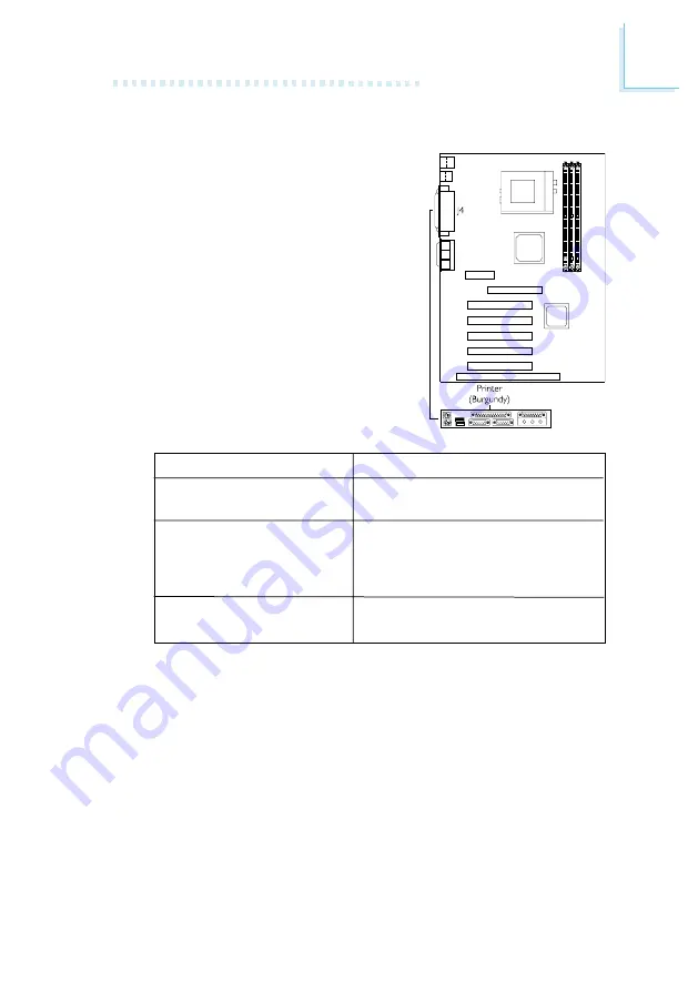
2.7.3  Parallel Port

The  system  board  has  a  standard

printer port (J4 - Burgundy) located at

the  ATX  double  deck  ports  of  the

board  for  interfacing  your  PC  to  a

parallel  printer.  It  supports  Normal,

ECP  and  EPP  modes. You  can  set  the

port’s mode in the Integrated Peripher-

als submenu of the BIOS.

2.7.4  Floppy Disk Drive Connector

The  system  board  is  equipped  with  a  shrouded  floppy  disk  drive

connector that supports two standard floppy disk drives. To prevent

improper floppy cable installation, the shrouded floppy disk header

has a keying mechanism. The 34-pin connector on the floppy cable

can  be  placed  into  the  header  only  if  pin  1  of  the  connector  is

aligned  with  pin  1  of  the  header. You  may  enable  or  disable  the

onboard  FDD  controller  in  the  Integrated  Peripherals  submenu  of

the BIOS.

Setting

Normal

ECP

(Extended  Capabilities

Port)

EPP

(Enhanced Parallel Port)

Function

Allows  normal  speed  operation

but in one direction only.
Allows parallel port to operate in

bidirectional  mode  and  at  a

speed  faster  than  the  SPP’s  data

transfer rate.
Allows  bidirectional  parallel  port

operation at maximum speed.

Содержание AK74-AC

Страница 1: ...AK74 SC Rev AF AK74 EC Rev A AK74 EN Rev A AK74 AC Rev A System Board User s Manual 43840104...

Страница 2: ...s to its contents at any time without obligation to notify any person or entity of such revisions or changes 2001 All Rights Reserved Trademarks Microsoft MS DOS WindowsTM Windows 95 Windows 98 Window...

Страница 3: ...ot installed and used in accordance with the instruction manual may cause harmful interference to radio communications However there is no guarantee that interference will not occur in a particular in...

Страница 4: ...ower 2 7 Ports and Connectors Chapter 3 Award BIOS Setup Utility 3 1 The Basic Input Output System 3 1 1 Standard CMOS Features 3 1 2 Advanced BIOS Features 3 1 3 Advanced Chipset Features 3 1 4 Integ...

Страница 5: ...dio Drivers and Software Application 4 5 Drivers and Utilities Installation Notes Appendix A Using the Suspend to RAM Function A 1 Using the Suspend to RAM Function Appendix B System Error Messages B...

Страница 6: ...600 650 700 750 800 850 900 950MHz 1GHz 1 2GHz or future processors AK74 AC AMD AthlonTM DuronTM 100 133MHz 200 266MHz DDR FSB processor 600 650 700 750 800 850 900 950MHz 1GHz 1 3GHz or future proces...

Страница 7: ...r 3D graphics applications AGP in this system board will deliver faster and better graphics to your PC AMR Audio Modem Riser is an interface designed for installing an audio riser card modem riser car...

Страница 8: ...e Wake On LAN connector One Wake On Ring connector CPU chassis and second chassis fan connectors Three internal audio connectors AUX in CD in and TAD AK74 SC EC AC PCI Bus Master IDE Controller Two PC...

Страница 9: ...op Management Interface DMI The system board comes with a DMI 2 0 built into the BIOS The DMI utility in the BIOS automatically records various information about your system configuration and stores t...

Страница 10: ...rotate This preventive measure has been added to protect the CPU from damage and insure a safe computing environment Refer to CPU Fan Connector with CPU Fan Protection Function in chapter 2 and CPU Fa...

Страница 11: ...in chapter 3 for more information Important If you are using a modem add in card the 5VSB power source of your power supply must support a minimum of 720mA RTC Timer to Power on the System The RTC ins...

Страница 12: ...you to use the Suspend to RAM function With the Suspend to RAM function enabled you can power off the system at once by pressing the power button or selecting Standby when you shut down Windows 98 200...

Страница 13: ...following items The system board A user s manual One IDE cable for ATA 33 ATA 66 or ATA 100 IDE drives One 34 pin floppy disk drive cable One Main Board Utility CD If any of these items are missing o...

Страница 14: ...14 Hardware Installation 2 1 System Board Layout Chapter 2 Hardware Installation AK74 SC VIA KT133 VT8363 and VT82C686A supports onboard audio...

Страница 15: ...Hardware Installation 15 AK74 EC VIA KT133 VT8363 and VT82C686B supports onboard audio...

Страница 16: ...16 Hardware Installation AK74 EN VIA KT133 VT8363 and VT82C686B...

Страница 17: ...stallation 17 AK74 AC VIA KT133 VT8363A and VT82C686B supports onboard audio Note The illustrations on the following pages are based on the AK74 SC EC AC system boards which are boards that support on...

Страница 18: ...subsequently increasing system performance Refer to chapter 1 System Memory section for detailed specification of the memory supported by the system board Warning Electrostatic discharge ESD can damag...

Страница 19: ...he module aligned with the keys on the socket 3 Seat the module vertically into the socket Make sure it is completely seated The tabs will hold the DIMM in place Pin 1 Notch Key Tab Tab 2 2 1 Installi...

Страница 20: ...ow 1 Power off the system and unplug the power cord 2 Set JP8 pins 2 and 3 to On Wait for a few seconds and set JP8 back to its default setting pins 1 and 2 On 3 Plug the power cord and power on the s...

Страница 21: ...If you are not using the onboard audio codec set this jumper pins 2 and 3 to On Disabled 2 3 On Clear CMOS Data 1 2 On Normal default 1 2 3 1 2 3 1 2 On Enable the Onboard Audio Codec default 2 3 On...

Страница 22: ...or Selecting the CPU s Front Side Bus AK74 AC CPU Front Side Bus Select Jumper JP10 This jumper is used to select the front side bus of the processor installed on the system board 1 2 1 2 On 100MHz 20...

Страница 23: ...2 6 Jumper Settings for Selecting the USB Power USB Power Select for USB 1 and USB 2 Jumper JP3 This jumper is used to select the power of the USB device connected to USB 1 or USB 2 2 3 On 5VSB 1 2 O...

Страница 24: ...er prior to connecting or disconnecting a mouse or keyboard Failure to do so may damage the system board 2 7 Ports and Connectors 2 7 1 Serial Ports The system board is equipped with onboard serial po...

Страница 25: ...drives To prevent improper floppy cable installation the shrouded floppy disk header has a keying mechanism The 34 pin connector on the floppy cable can be placed into the header only if pin 1 of the...

Страница 26: ...Drive Cable 1 If you are connecting two IDE disk drives install the 40 pin connector of the IDE cable into the primary shrouded IDE header J21 If you are adding a third or fourth IDE device install t...

Страница 27: ...jumpers and or switches on the drives The AK74 SC system board supports Enhanced IDE or ATA 2 ATA 33 and ATA 66 hard drives while AK74 EC EN AC supports Enhanced IDE or ATA 2 ATA 33 ATA 66 and ATA 10...

Страница 28: ...ouble deck ports of the board The J19 connector on the system board allows you to connect the optional 3rd and 4th USB ports These optional USB ports which are mounted on a card edge bracket will be p...

Страница 29: ...board Set UART2 Mode Select in the Integrated Peripherals submenu of the BIOS to the type of IrDA standard supported by your device You must have the proper drivers installed in your operating system...

Страница 30: ...llow the steps below 1 Before you power on the system make sure the heatsink and CPU fan are correctly installed onto the CPU The system is capable of monitoring the CPU fan therefore you must use a f...

Страница 31: ...or it took some time before the fan rotated check whether the heatsink and fan are mounted properly onto the CPU then restart the system If the same problem occurs you must replace it with a good qual...

Страница 32: ...nector to location J23 on the system board The fan will provide adequate airflow throughout the chassis to prevent overheating the processor The system is capable of monitoring and controlling the spe...

Страница 33: ...to the 15 pin D sub connector J9 Gold located at the ATX double deck ports of the system board This port works well with any application that is compatible with the standard PC joystick 2 7 10 Second...

Страница 34: ...e out Jack J6 Lime This jack is used to connect external amplifier speakers Line in Jack J7 Light Blue This jack can be connected to any external audio devices such as Hi fi set CD player AM FM radio...

Страница 35: ...s are used to receive audio from a CD ROM drive TV tuner or MPEG card TAD TAD is a connector for telephony audio devices such as voice modem cards By installing a PCI voice modem card that is also equ...

Страница 36: ...you must enable Resume on LAN Ring Wake Up Events field in the Power Management Setup of the BIOS Your LAN card package should include a cable Connect one end of the cable to the wakeup header on the...

Страница 37: ...ion connect one end of the cable that came with the card to the card s wake on ring connector and the other end to location J12 on the system board You must also enable Resume on LAN Ring Wake Up Even...

Страница 38: ...n red when the system is in the power on Soft Off or Suspend Power On Suspend or Suspend to RAM state 3 3VSB Standby for PCI Jumper JP1 The default setting of jumper JP1 is On It provides 3 3VSB Stand...

Страница 39: ...wer connector is shown below Pin 1 2 3 4 5 6 7 8 9 10 Function 3 3V 3 3V Ground 5V Ground 5V Ground PW OK 5VSB 12V Pin 11 12 13 14 15 16 17 18 19 20 Function 3 3V 12V Ground PS ON Ground Ground Ground...

Страница 40: ...te ATX SW ATX Power Switch Depending on the setting in the BIOS setup this switch is a dual function power button that will allow your system to enter the Soft Off or Suspend mode Refer to Soft Off By...

Страница 41: ...y indicate that the CPU or memory module was not installed properly Please make sure they are properly inserted into their corresponding socket Pin 1 2 3 4 5 6 7 8 9 10 11 12 13 14 15 16 17 18 19 20 2...

Страница 42: ...t the system or press the Reset button You may also restart the system by pressing the Ctrl Alt and Del keys simultaneously When you press Del the main menu screen will appear 3 1 1 Standard CMOS Feat...

Страница 43: ...ndary Slave field then press Enter IDE HDD Auto Detection Detects the parameters of the drive The parameters will automatically be shown on the screen The settings on the screen are for reference only...

Страница 44: ...rating system s manual or Help desk on which one to select Drive A and Drive B These fields identify the types of floppy disk drives installed None No floppy drive is installed 360K 5 25 in 5 1 4 in s...

Страница 45: ...But Diskette The system boot will not stop for a disk error it will stop for all other errors All But Disk Key The system boot will not stop for a disk or keyboard error it will stop for all other err...

Страница 46: ...isable this field Also disable this field if you are installing or running certain operating systems like Windows 95 98 2000 ME or the operating system may not install nor work CMOS Setup Utility Copy...

Страница 47: ...ond Boot Device and Third Boot Device fields respectively The BIOS will boot the operating system according to the sequence of the drive selected Set Boot Other Device to Enabled if you wish to boot f...

Страница 48: ...o accelerate cursor movements with the arrow keys You can then select the typematic rate and typematic delay in the Typematic Rate Chars Sec and Typematic Delay Msec fields below Typematic Rate Chars...

Страница 49: ...s SMART Self Monitoring Analysis and Reporting Technology hard drives SMART is a reliability prediction technology for ATA IDE and SCSI drives The drive will provide sufficient notice to the system or...

Страница 50: ...e memory size memory speed etc When this field is enabled the system will run according to the information in the EEPROM Disabled It allows you to configure the 2 fields that follow SDRAM Cycle Length...

Страница 51: ...rt this function leave this field in its default setting Disabled AGP Aperture Size This field is relevant to the memory mapped graphics data of the AGP card installed in your system Leave this in its...

Страница 52: ...USB Keyboard Support is Disabled However if you are using a USB keyboard under DOS make sure to enable this function OnChip Sound AK74 SC EC AC By default this field is set to Auto the onboard sound...

Страница 53: ...are for reference only Your version may not be identical to this one X X CMOS Setup Utility Copyright C 1984 2000 Award Software Integrated Peripherals Item Help Menu Level Move F6 Fail Safe Defaults...

Страница 54: ...n Auto is selected the BIOS will select the best available option after checking your hard drive or CD ROM Auto The BIOS will automatically detect the settings for you Disabled The BIOS will not detec...

Страница 55: ...make sure this field is set to Normal To use the IrDA function follow the steps below 1 Connect your IrDA cable to connector J22 on the system board 2 Set the UART2 Mode Select field to the type of I...

Страница 56: ...ion at maximum speed ECP Mode Use DMA This is used to select a DMA channel for the parallel port The options are 1 and 3 Default setting 3 EPP Mode Select The options are EPP1 9 and EPP1 7 Default set...

Страница 57: ...tions are DMA 0 DMA 1 DMA 2 and DMA 3 MPU 401 This field is used to enable or disable MPU 401 MPU 401 I O Address This field is used to select MPU 401 s I O address The options are 330 333H 300 303H 3...

Страница 58: ...ve the cursor to this field and press Enter The Power Management HDD Power Down Doze Mode and Suspend Mode fields will appear Power Management This field allows you to select the type or degree of pow...

Страница 59: ...2 of full speed while all other devices still operate at full speed Suspend Mode This is selectable only when the Power Management field is set to User Define When the system enters the Suspend mode a...

Страница 60: ...Select this if your video board supports it MODEM Use IRQ This field is used to set an IRQ channel IRQ 3 4 5 7 9 10 or 11 for the modem installed in your system Soft Off by PWRBTN This field allows yo...

Страница 61: ...If the system s power is on when AC power failure occurs the system will power on when power returns Wake Up Events Move the cursor to this field and press Enter The following fields will appear USB R...

Страница 62: ...te of Month and Resume Time hh mm ss fields However if the system is being accessed by incoming calls or the network prior to the date and time set in these fields the system will give priority to the...

Страница 63: ...ion Data Resources Controlled By IRQ Resources PCI VGA Palette Snoop Assign IRQ For VGA Assign IRQ For USB Disabled Auto ESCD Press Enter Disabled Enabled Enabled Item Help Menu Level Default is Disab...

Страница 64: ...lette Snoop This field determines whether the MPEG ISA VESA VGA cards can work with PCI VGA or not The default value is Disabled Enabled MPEG ISA VESA VGA cards work with PCI VGA Disabled MPEG ISA VES...

Страница 65: ...for the USB device connected to your system However if you are not using USB devices and an ISA slot requires an IRQ set this field to Disabled The IRQ previously occupied by the USB device will be av...

Страница 66: ...s you must install the VIA Hardware Monitor utility This utility is included in the CD that came with the system board Refer to VIA Hardware Monitor in chapter 4 for more information The settings on t...

Страница 67: ...el in order to enter the main menu of the BIOS If you did not press Del the system will automatically power off after the 5 warning beeps You may either 1 Press Del then enter a new CPU temperature li...

Страница 68: ...Values PU PD Value F10 Save ESC Exit CPU Vcore Select This field allows you to manually adjust to a higher core voltage that is supplied to the CPU If you wish to use the CPU s default core voltage le...

Страница 69: ...o provide better system performance If you selected an option other than Default and is unable to boot up the system there are 2 methods of going back to its default setting Method 1 Clear the CMOS da...

Страница 70: ...option in the main menu and press Enter The message below will appear Load Fail Safe Defaults Y N N If you want to proceed type Y and press Enter The default settings will be loaded 3 1 10 Load Optim...

Страница 71: ...n exactly the same password If you type in a wrong password you will be prompted to enter the correct password again To delete or disable the password function highlight Set Supervisor Password and pr...

Страница 72: ...t Without Saving Y N N Type Y and press Enter The system will reboot and you will once again see the initial diagnostics on the screen If you wish to make any changes to the setup press Ctrl Alt Esc s...

Страница 73: ...mbers of hardware installed etc are automatically detected and stored in the DMI pool which is a part of the system board s Plug and Play BIOS Additional information such as ISA based peripherals whic...

Страница 74: ...arrow keys then press Enter 3 The cursor will move to the screen you select allowing you to edit information The screen will also display the auto detected information 4 Press F10 to update the edite...

Страница 75: ...or arrow keys to select the Load DMI File menu 2 The following message will appear Press Enter to select DMI file for load Press Enter 3 The DMI files will appear on the screen Select the file you wou...

Страница 76: ...or Windows NT 4 0 operating system To install the utility insert the CD into a CD ROM drive The autorun screen Main Board Utility CD will appear Click the VIA Hardware Monitor button to install the ut...

Страница 77: ...nsert the CD that came with the system board package into a CD ROM drive The autorun screen Main Board Utility CD will appear 2 Click VIA Service Pack 3 The Welcome screen will appear Click Next Pleas...

Страница 78: ...the Main Board Utility CD screen did not appear please go directly to the root directory of the CD and double click Setup 2 Please go to DFI s web site at http www dfi com support download1 asp for th...

Страница 79: ...eviously installed Windows 98 2000 ME you need to upgrade the system in order to support ACPI Please contact Microsoft for upgrade information The settings on the screen are for reference only Your ve...

Страница 80: ...the cursor to Settings then click Control Panel To check whether ACPI was properly installed double click the System icon In the System Properties dialog box click the Device Manager tab In View devi...

Страница 81: ...g box Double click the Power Management icon 11 Click the Advanced tab In the When I press the power button on my computer field select Standby 9 Click File System In the Typical role of this computer...

Страница 82: ...computer at once by pressing the power button or selecting Standby when you shut down Windows 98 2000 ME To power on the computer just press the power button The operating session where you left off...

Страница 83: ...consists of a single long beep B 2 Error Messages One or more of the following messages may be displayed if the BIOS detects an error during the POST This list indicates the error messages for all Aw...

Страница 84: ...fixed disk Hard Disk s fail 08 Sector Verify failed Keyboard is locked out Unlock the key The BIOS detects that the keyboard is locked Keyboard controller is pulled low Keyboard error or no keyboard...

Страница 85: ...ed on 5 The display s brightness and contrast controls are adjusted properly 6 All add in boards in the expansion slots are seated securely 7 Any add in board you have installed is designed for your s...

Страница 86: ...ertical sync 2 Move away any objects such as another monitor or fan that may be creating a magnetic field around the display 3 Make sure your video card s output frequencies are supported by this moni...

Страница 87: ...ble first hard drive is configured as Master and the second hard drive is configured as Slave The master hard drive must have an active bootable partition Excessively long formatting period 1 If your...

Страница 88: ...s setting 4 Make sure the COM settings and I O address are configured correctly Keyboard Nothing happens when a key on the keyboard was pressed 1 Make sure the keyboard is properly connected 2 Make su...

Отзывы: