


Installation
Install the valve between ASME Class 125 or Class 150 pipeline flanges, or other flanges that match
valve end connection. Flange gaskets are required. Before installation, remove foreign material such
as weld spatter, oil, grease, and dirt from the valve and pipeline.
Normal Installations
Install the valve so that the side marked “SEAT” is on the lower pressure side of the valve when the
valve is closed; the pipeline pressure will then help seal the valve in the closed position.
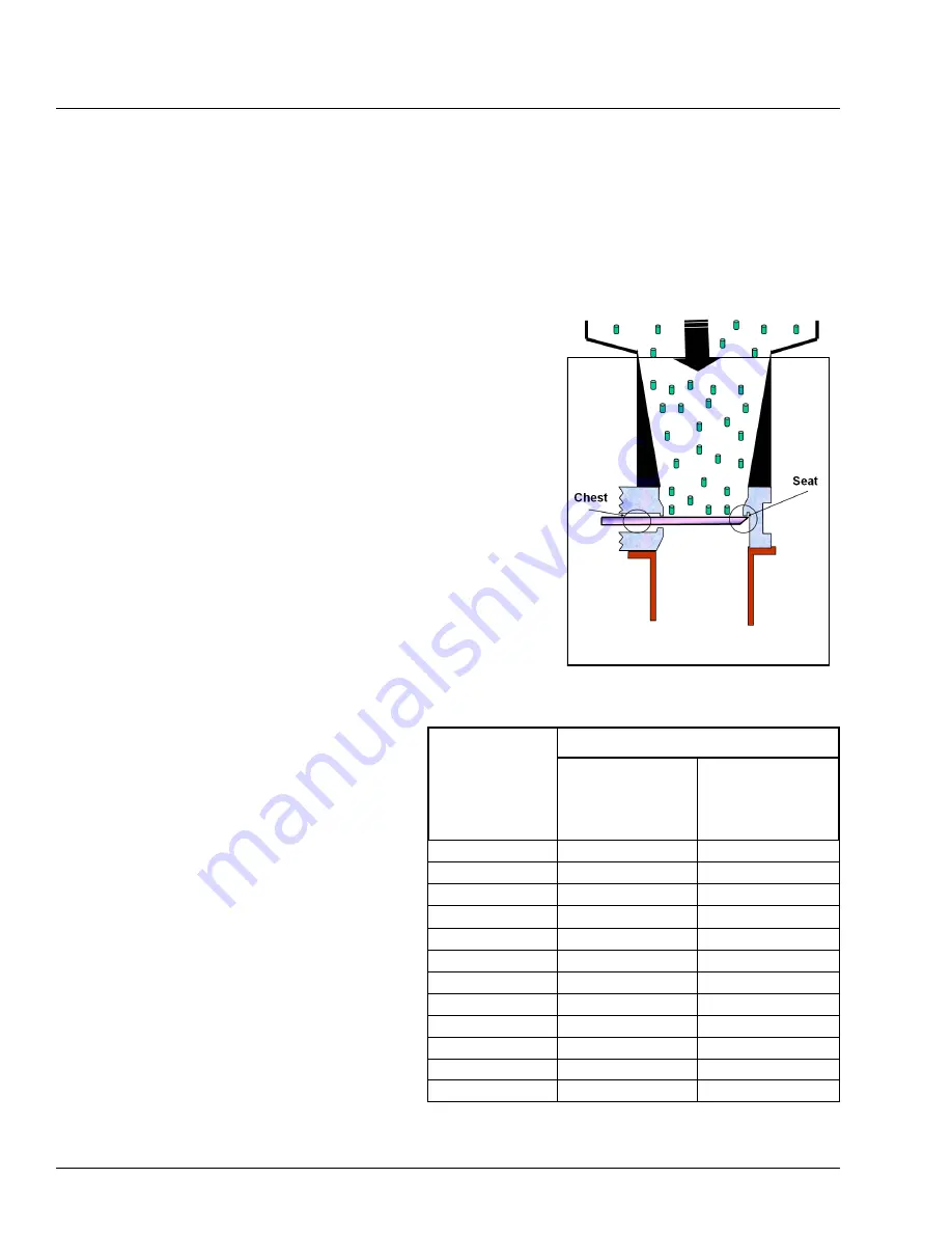
Gravity (Dry) Service Installations
When installing the valve in a vertical pipeline (such as a hopper
bottom, gravity flow, or other dry service application), install the
SEAT side of the valve facing upstream as shown in Figure 1.
Installing the valves with the seat side upstream prevents process
media buildup in the seat and chest area of the valve. This orien-
tation also allows the seat to act as an integral deflection cone,
protecting the seat from wear.
General Guidelines
Observe the following points to prevent distortion of the valve
body and gate when the flange bolts are tightened:
Align the mating pipeline flanges.
Select the length of the flange bolts so that the bolts
used in the blind holes near the chest area of the valve
do not bottom out when tightened.
We recommend using studs with
nuts in the blind holes.
Tighten the flange bolts evenly, in a
crisscross pattern. Refer to Table A
for recommended flange bolt/stud
torques.
Note:
Torque ranges are based on ASME
Pressure Vessel Code Calculations and
lab test data. These torques are only for
the listed gasket types. For other gasket
types listed in ASME, consult DeZURIK.
After installing the valve, pressurize pipeline
and ensure the packing is not leaking. If the
packing leaks, adjust the packing as described
on the next page.
D10411
Page 6
June 2019
DeZURIK
2-24” KGC ES or HD KNIFE GATE VALVES
Valve Size
ASME Gasket Types
Rubber with
Soft Fabric
Filler, & 1/8”
Thick Hard
Soft Elastomer
Gasket Shore
Durometer < 75A
2” (50mm)
26 - 29
8 - 9
3” (80mm)
37 - 41
14 - 16
4” (100mm)
26 - 29
11 - 12
6” (150mm)
41 - 45
22 - 24
8” (200mm)
55 - 61
35 - 39
10” (250mm)
56 - 62
40 - 44
12” (300mm)
80 - 88
59 - 65
14” (350mm)
107 - 118
81 - 89
16” (400mm)
103 - 114
79 - 87
18” (450mm)
128 - 141
102 - 112
20” (500mm)
123 - 136
99 - 109
24” (600mm)
188 - 207
155 - 171
Table A: Recommended Flange Bolt/Stud
Torque Range in ft-lbs (non-lubricated)
Figure 1—Vertical Line/
Hopper Bottom